AT INTERFACE DESCRIPTION

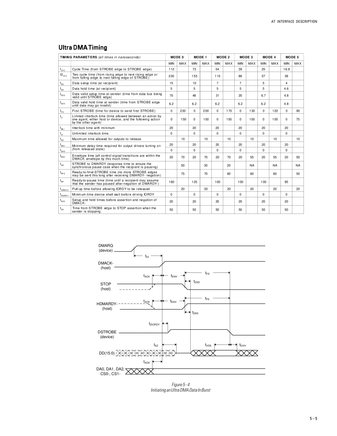
Ultra DMA Timing

T IM IN G PARAMET ERS (all tim es in nanoseconds )

MODE 0

MODE 1

MODE 2

MODE 3

MODE 4

MODE 5


MIN

MAX

MIN

MAX

MIN

MAX

MIN

MAX

MIN

MAX

MIN

MAX


tCYC

Cycle Time (from STROBE edge to STROBE edge)

112


73


54


39


25


16.8


t2CYC

Two cycle time (from ris ing edge to next ris ing edge or

230


153


115


86


57


38


from falling edge to next falling edge of STROBE )


tDS

D ata s etup time (at rec ipient)

15


10


7


7


5


4


tDH

D ata hold time (at rec ipient)

5


5


5


5


5


4.6


tDVS

D ata valid setup time at sender (time from data bus being

70


48


31


20


6.7


4.8


valid until STROBE edge)


tDVH

Data valid hold time at sender (time from STROBE edge

6.2


6.2


6.2


6.2


6.2


4.8


until data may go invalid)


tF S

Firs t STROBE (time for device to send first STROBE)

0

230

0

200

0

170

0

130

0

120

0

90

tL I

Limited interlock time (time allowed between an action by

0

150

0

150

0

150

0

100

0

100

0

75


one agent, either host or device, and the following action


by the other agent)


tML I

Interlock time with minimum

20


20


20


20


20


20


tUI

Unlimited interlock time

0


0


0


0


0


0


tAZ

Maxim um time allowed for outputs to release


10


10


10


10


10


10

tZAH

Minimum delay time required for output drivers turning on

20


20


20


20


20


20


tZ AD

(from releas ed state)

0


0


0


0


0


0


tENV

Envelope time (all control signal transitions are within the

20

70

20

70

20

70

20

55

20

55

20

50


D MACK envelope by this much time)


tSR

STROBE to D MARDY (response time to ensure the


50


30


20


NA


NA


NA


synchronous pause case when the rec ipient is pausing)


tRF S

Ready-to-final -STROBE time (no more STROBE edges


75


70


60


60


60


50


may be sent this long after receiving D MARDY- negation)


tRP

Ready-to-pause time (time until a recipient may assume

160


125


100


100


100


85


that the sender has paused after negation of D MARDY-)


tIORDYZ

Pull-up time before allowing IORD Y to be releas ed


20


20


20


20


20


20

tZ IORD Y

Minim um time device shall wait before driving IORDY

0


0


0


0


0


0


tACK

Setup and hold times before assertion and negation of

20


20


20


20


20


20


DMAC K-


tSS

Time from STROBE edge to STOP assertion when the

50


50


50


50


50


50


sender is stopping


DMARQ


(device)


tUI


DMACK-


(host)


tACK

tENV

STOP


(host)


tACK

tENV

HDMARDY-


(host)


tZIORDY


DSTROBE


(device)


tAZ


DD(15:0)


tACK


DA0, DA1, DA2,


CS0-, CS1-


tFS

tZAD


tFS


tZAD


tVDS

tDVH

Figure 5 - 4

Initiating an Ultra DMA Data In Burst

5 – 5

Page 30
Image 30
Maxtor 98196H8, 96147H6 specifications Ultra DMA Timing, Mode

96147H6, 98196H8 specifications

The Maxtor 98196H8 and 96147H6 are notable hard drive models that were part of Maxtor's diverse range of storage solutions. Both models were designed to cater to various computing needs and display characteristics that made them reliable, high-performance options during their time in the market.

The Maxtor 98196H8 is a 19.1 GB hard drive that utilizes the IDE interface, which is known for its ease of use and compatibility with a broad range of motherboards. This model features a rotational speed of 5400 RPM, striking a balance between performance and power consumption. With a data transfer rate of up to 33 MB/s, the 98196H8 is capable of efficiently handling average workloads, making it suitable for everyday computing tasks such as word processing, web browsing, and media playback.

One standout characteristic of the 98196H8 is its shock protection technology, which enhances durability and reduces the risk of data loss from accidental drops. The drive uses fluid dynamic bearing (FDB) motors for quieter operation and increased reliability. Additionally, Maxtor's proprietary technology, including the SoftSonic feature, allows for reduced operational noise levels, making it an appealing choice for users who prioritize a quiet working environment.

On the other hand, the Maxtor 96147H6 boasts a slightly larger capacity of 14.7 GB and shares similar interface traits and rotational speed as the 98196H8. With a focus on providing reliable storage for desktop applications, this model leverages Maxtor's advanced data recovery solutions, which help ensure that users can restore lost data in the event of drive failures. Its high-capacity storage makes it well-suited for users dealing with larger files or needing additional space for various applications and media.

Both models are equipped with Maxtor's Error Recovery Control technology, which actively manages potential read/write errors, ensuring data integrity during storage and retrieval processes. This is especially beneficial for users handling critical information or relying on the storage for important projects.

In conclusion, the Maxtor 98196H8 and 96147H6 hard drives exemplified Maxtor's dedication to creating dependable storage solutions for consumers. With their variety of capacities, advanced technologies, and characteristics tailored to improve reliability and performance, they served many users well during their availability in the market.