Installation
For systems using Serial ATA cables, the Serial ATA II specification mandates that host systems connecting to disk drives using SATA cables must ground Pin 11, resulting in disabling staggered
In backplane
Where Pin 11 has been grounded, but the system builder wants Staggered
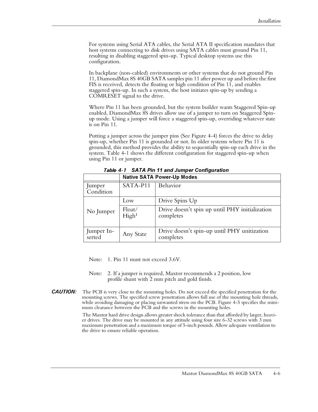
Putting a jumper across the jumper pins (See Figure
Table
| Native SATA | ||
|
|
| |
Jumper |
| Behavior | |
Condition |
|
| |
|
|
| |
| Low | Drive Spins Up | |
|
|
| |
No Jumper | Float/ | Drive doesn’t spin up until PHY initialization | |
High1 | completes | ||
| |||
|
|
| |
Jumper In- | Any State | Drive doesn’t | |
serted | completes | ||
| |||
|
|
| |
Note: 1. Pin 11 must not exceed 3.6V.
Note: 2. If a jumper is required, Maxtor recommends a 2 position, low profile shunt with 2 mm pitch and gold finish.
CAUTION: The PCB is very close to the mounting holes. Do not exceed the specified penetration for the mounting screws. The specified screw penetration allows full use of the mounting hole threads, while avoiding damaging or placing unwanted stress on the PCB. Figure
The Maxtor hard drive design allows greater shock tolerance than that afforded by larger, heavi- er drives. The drive may be mounted in any attitude using four size
Maxtor DiamondMax 8S 40GB SATA |
