CHAP. 2 Function of Each Button
2-2. REAR
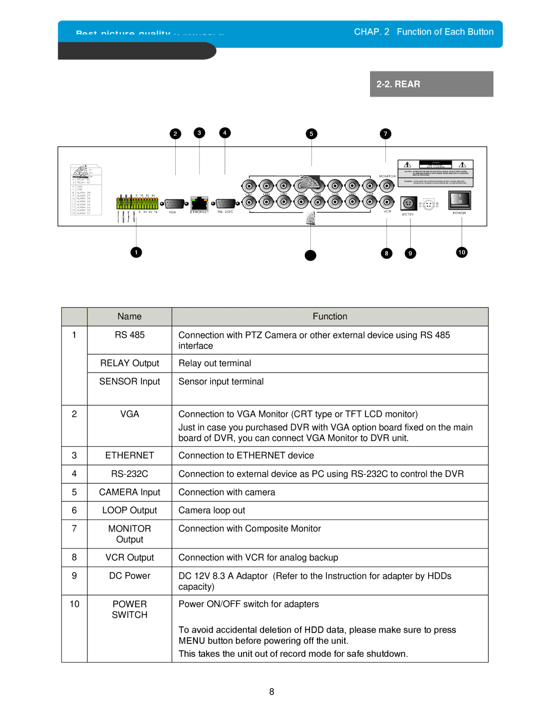
| Name | Function |
|
|
|
1 | RS 485 | Connection with PTZ Camera or other external device using RS 485 |
|
| interface |
|
|
|
| RELAY Output | Relay out terminal |
|
|
|
| SENSOR Input | Sensor input terminal |
|
|
|
2 | VGA | Connection to VGA Monitor (CRT type or TFT LCD monitor) |
|
| Just in case you purchased DVR with VGA option board fixed on the main |
|
| board of DVR, you can connect VGA Monitor to DVR unit. |
|
|
|
3 | ETHERNET | Connection to ETHERNET device |
|
|
|
4 | Connection to external device as PC using | |
|
|
|
5 | CAMERA Input | Connection with camera |
|
|
|
6 | LOOP Output | Camera loop out |
|
|
|
7 | MONITOR | Connection with Composite Monitor |
| Output |
|
|
|
|
8 | VCR Output | Connection with VCR for analog backup |
|
|
|
9 | DC Power | DC 12V 8.3 A Adaptor (Refer to the Instruction for adapter by HDDs |
|
| capacity) |
|
|
|
10 | POWER | Power ON/OFF switch for adapters |
| SWITCH |
|
|
| To avoid accidental deletion of HDD data, please make sure to press |
|
| MENU button before powering off the unit. |
|
| This takes the unit out of record mode for safe shutdown. |
|
|
|
8