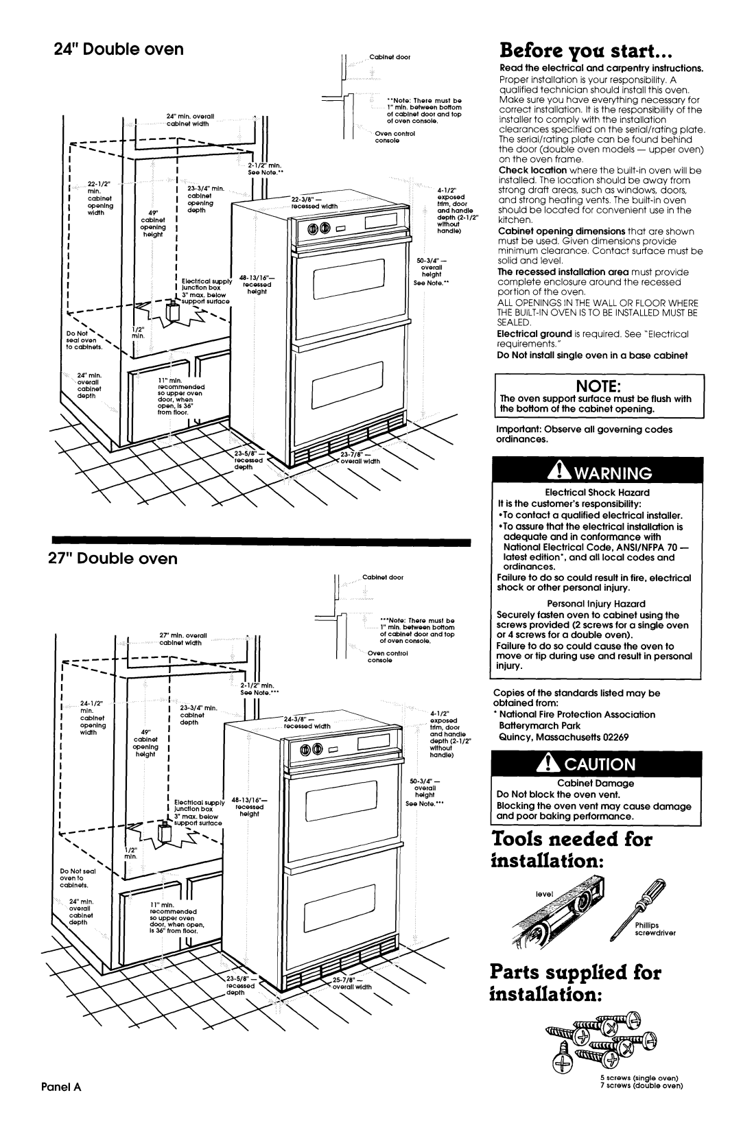
24” Double oven


24” mln. overall


q----


I

-N

-I

i-r


i


See

Note.”

I


22-l/2”

1


I


1

2%j/4”

min.


min.


I


cabinet


I

cabinet


openlng

I

z$::g


width

44’


1

I


cabinet


openlng

I


helght

I


i


I


supply I


I

Electdcal

sed


I

lunctton

box


Iht

rc--


b.


\

\


lo

Not’,


\


ieal

oven


o cabinets.

\


24’

mln.


overall

recommended


cabinet


so upper

oven


door,

when

I


open,

Is 38

I


_

_.


rrom

rroor.


Cablnet door

“Note: There must be 1” min. between bottom ot cablnet door and top ot oven console.

Oven control

I I

console

4-112” exposed trtm. door and handle depth (2-l/2” wlthout handle)

50-W4” - overall

See Note.”

Before you start...

Read the electrical and carpentry instructions. Proper installation is your responsibility. A qualified technician should install this oven. Make sure you have everything necessary for correct installation. It is the responsibility of the installer to comply with the installation clearances specified on the serial/rating plate. The serial/rating plate can be found behind the door (double oven models - upper oven) on the oven frame.

Check location where the built-in oven will be installed. The location should be away from strong draft areas, such as windows, doors, and strong heating vents. The built-in oven should be located for convenient use in the kitchen.

Cabinet opening dimensions that are shown must be used. Given dimensions provide minimum clearance. Contact surface must be solid and level.

The recessed installation area must provide complete enclosure around the recessed portion of the oven.

ALL OPENINGS IN THE WALL OR FLOOR WHERE THE BUILT-IN OVEN IS TO BE INSTALLED MUST BE SEALED.

Electrical ground is required. See “Electrical requirements.”

Do Not install single oven in a base cabinet

NOTE:

lhe oven support surface must be flush with the bottom of the cabinet opening.

Important: Observe all governing codes ordinances.

Electrical Shock Hazard

It is the customer’s responsibility:

*To contact a qualified electrical installer. *To assure that the electrical installation is

27” Double oven


I


27’

mln.

overall

i


cabinet

wldth


I


1” mln.


rlote.“‘

I


24-112”


I

23.j/4”

mln.


mln.


I

cabinet


cabinet


I


depth


openlng

I


I


49”


width


I


I


cabinet


I


opening

I


I


helght

I


I


I


I


I


I


If-

I


Electrlcal

supply


I

junctton

box

I

1L

c-4-C

\

\

\ \ \

Do Not seal oven to cabinets.

24” mtn.

overall. .recommended so upper oven door, when open, Is 36” lrom (loor.

Cablnet door

“‘Note: There must be 1” mln. between bottom ol cabinet door and top ol oven console.

Oven control console

4-l/2”

exDosed

tdti, door and handle depth (2-l/2” wlthout handle)

50-j/4” - overall

Ihelght See Note.“’

adequate and in conformance with National Electrical Code, ANSI/NFPA 70 - latest edition*, and all local codes and ordinances.

Failure to do so could result in fire, electrical shock or other personal injury.

Personal Injury Hazard Securely fasten oven to cabinet using the screws provided (2 screws for a single oven or 4 screws for a double oven).

Failure to do so could cause the oven to move or tip during use and result in personal injury.

Copies of the standards listed may be obtained from:

l National Fire Protection Association Batterymarch Park

Quincy, Massachusetts 02269

Cabinet Damage

Do Not block the oven vent.

Blocking the oven vent may cause damage and poor baking performance.

Tools needed for installation:

overall wrarn

Parts supplied for installation:

5 screws (single oven)

Panel A

7 screws (double oven)

Page 2
Image 2
Maytag 3183636 Before you start, Tools needed for installation, Parts supplied for installation, Double oven

3183636 specifications

The Maytag 3183636 is a highly acclaimed component specifically designed for various Maytag appliances, particularly in the realm of laundry solutions. Known for its durability and reliability, this part plays a critical role in ensuring optimal performance and user satisfaction.

One of the standout features of the Maytag 3183636 is its robust construction. It is engineered to withstand the rigors of daily use, providing users with peace of mind that they can depend on their appliance to function seamlessly over the long term. Made from high-quality materials, the part is resistant to wear and tear, making it a smart investment for those looking to maintain the longevity of their washing machines or dryers.

In terms of compatibility, the Maytag 3183636 is designed to fit several models, making it a versatile option for consumers. This compatibility means that users do not have to worry about whether this part will function with their particular appliance, as it is suitable for a wide range of Maytag units. This adaptability is a significant advantage in households that value efficiency and convenience.

One notable technological advancement is its integration with the manufacturer's commitment to energy efficiency and eco-friendly designs. The Maytag 3183636 supports these initiatives by enabling appliances to operate more efficiently, thus reducing energy consumption. This not only contributes to lower utility bills but also aligns with contemporary environmental standards.

Another characteristic of the Maytag 3183636 is its ease of installation. Designed with the user in mind, it features a straightforward design that allows for quick and hassle-free replacement. This feature is especially beneficial for homeowners who prefer to conduct their own repairs rather than hire a professional. The clear instructions that accompany the product further simplify the installation process, giving users confidence in their ability to manage appliance maintenance.

Overall, the Maytag 3183636 represents a blend of innovation, durability, and user-friendliness. With its well-thought-out features and technologies, it not only enhances the performance of Maytag appliances but also embodies the brand's commitment to quality and customer satisfaction. Whether you are in need of a replacement part or looking to ensure the continued efficiency of your laundry appliances, the Maytag 3183636 stands out as an excellent choice for consumers.