| Recessed Area and Closet Installation Instructions |
| Product Dimensions | ||||||
|
|
|
|
|
|
|
|
|
|
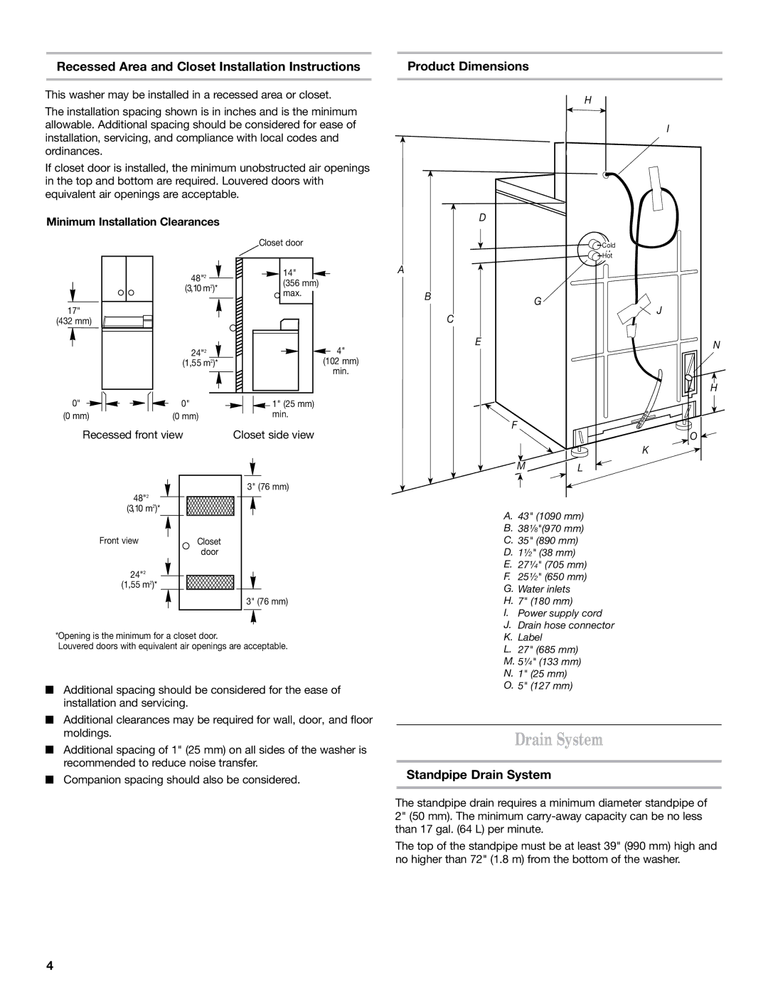
This washer may be installed in a recessed area or closet. |
|
|
|
|
|
|
|
| |
|
|
|
| H |
|
|
| ||
The installation spacing shown is in inches and is the minimum |
|
|
|
|
| ||||
|
|
|
|
|
|
|
| ||
allowable. Additional spacing should be considered for ease of |
|
|
|
|
|
|
|
| |
|
|
|
|
|
| I |
| ||
installation, servicing, and compliance with local codes and |
|
|
|
|
|
|
| ||
|
|
|
|
|
|
|
| ||
ordinances. |
|
|
|
|
|
|
|
| |
If closet door is installed, the minimum unobstructed air openings |
|
|
|
|
|
|
|
| |
in the top and bottom are required. Louvered doors with |
|
|
|
|
|
|
|
| |
equivalent air openings are acceptable. |
|
|
|
|
|
|
|
| |
|
|
|
|
|
|
|
|
|
|
| Minimum Installation Clearances |
|
| D | |||||
|
|
|
|
|
|
|
|
| |
|
| Closet door |
|
|
| Cold |
|
|
|
|
|
| Hot |
| 48"2 | 14" |
| A |
|
|
|
|
|
|
| ||
| (3,10 m2)* | (356 mm) |
| B |
|
|
|
| max. |
| G |
| |
17" |
|
|
|
| J | |
|
|
| C |
| ||
(432 mm) |
|
|
|
|
| |
| 24"2 |
| 4" | E |
| N |
|
|
|
| |||
|
|
|
|
| ||
| (1,55 m2)* |
| (102 mm) |
|
|
|
|
|
| min. |
|
|
|
|
|
|
|
|
| H |
0" | 0" | 1" (25 mm) |
|
|
|
|
(0 mm) | (0 mm) | min. |
| F |
|
|
Recessed front view | Closet side view |
|
| O | ||
|
|
| ||||
|
|
|
|
|
| K |
|
|
|
|
| M | L |
|
| 3" (76 mm) |
|
|
|
|
48"2 |
|
|
|
|
|
|
(3,10 m2)* |
|
|
| A. 43" (1090 mm) | ||
|
|
|
| |||
|
|
|
| B. 38¹⁄8"(970 mm) | ||
Front view | Closet |
|
| C. 35" (890 mm) | ||
| door |
|
| D. 1¹⁄2" (38 mm) |
| |
24"2 |
|
|
| E. 27¹⁄4" (705 mm) | ||
|
|
| F. 25¹⁄2" (650 mm) | |||
(1,55 m2)* |
|
|
| G. Water inlets |
| |
|
|
|
|
| ||
|
| 3" (76 mm) |
| H. 7" (180 mm) |
| |
|
|
|
| I. | Power supply cord | |
*Opening is the minimum for a closet door. |
|
| J. Drain hose connector | |||
|
| K. Label |
| |||
Louvered doors with equivalent air openings are acceptable. |
| L. 27" (685 mm) | ||||
|
|
|
| M. 5¹⁄4" (133 mm) | ||
|
|
|
| N. 1" (25 mm) |
| |
Additional spacing should be considered for the ease of | O. | 5" (127 mm) |
| |||
|
|
| ||||
installation and servicing. |
|
|
|
|
| |
Additional clearances may be required for wall, door, and floor moldings.
Additional spacing of 1" (25 mm) on all sides of the washer is recommended to reduce noise transfer.
Companion spacing should also be considered.
Drain System
Standpipe Drain System
The standpipe drain requires a minimum diameter standpipe of 2" (50 mm). The minimum
The top of the standpipe must be at least 39" (990 mm) high and no higher than 72" (1.8 m) from the bottom of the washer.
4
