2.Attach one adapter to the gas pressure regulator and the other adapter to the gas shutoff valve. Tighten both adapters.
3.Use a ¹⁵⁄₁₆" combination wrench and channel lock pliers to attach the flexible connector to the adapters. Check that connector is not kinked.
IMPORTANT: All connections must be
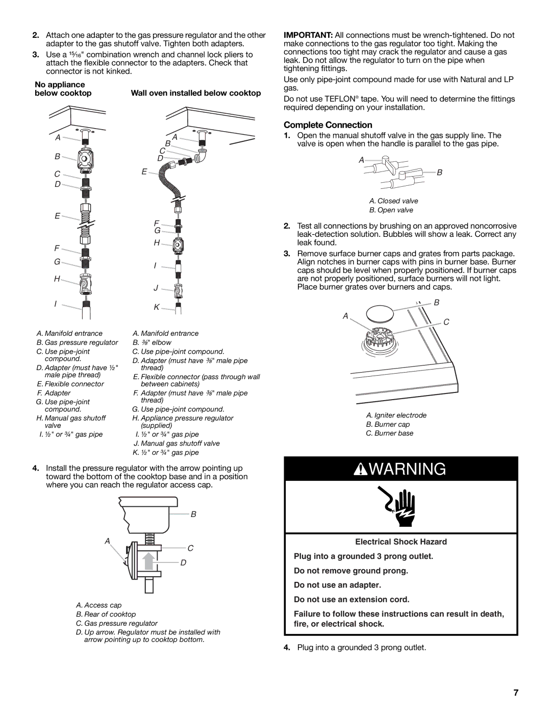
No appliance below cooktop
A ![]()
B![]()
![]()
C![]()
D![]()
![]()
E![]()
F
G
H
I
A. Manifold entrance
B. Gas pressure regulator
C. Use
compound.
D. Adapter (must have ½" male pipe thread)
E. Flexible connector F. Adapter
G. Use
H. Manual gas shutoff valve
I. ½" or ¾" gas pipe
Wall oven installed below cooktop
A
B
C![]()
D ![]()
![]()
![]()
E
F![]()
![]()
G ![]()
H![]()
I![]()
![]()
J![]()
![]()
K![]()
![]()
A.Manifold entrance
B.³⁄₈" elbow
C.Use
D.Adapter (must have ³⁄₈" male pipe thread)
E.Flexible connector (pass through wall between cabinets)
F.Adapter (must have ³⁄₈" male pipe thread)
G.Use
H.Appliance pressure regulator (supplied)
I.½" or ¾" gas pipe
J.Manual gas shutoff valve
K.½" or ¾" gas pipe
Use only
Do not use TEFLON® tape. You will need to determine the fittings required depending on your installation.
Complete Connection
1.Open the manual shutoff valve in the gas supply line. The valve is open when the handle is parallel to the gas pipe.
A
B
A. Closed valve
B. Open valve
2.Test all connections by brushing on an approved noncorrosive
3.Remove surface burner caps and grates from parts package. Align notches in burner caps with pins in burner base. Burner caps should be level when properly positioned. If burner caps are not properly positioned, surface burners will not light.
Place burner grates over burners and caps.
B
A
C
A. Igniter electrode
B. Burner cap
C. Burner base
4.Install the pressure regulator with the arrow pointing up toward the bottom of the cooktop base and in a position where you can reach the regulator access cap.
B
A
C
D
A. Access cap
B. Rear of cooktop
C. Gas pressure regulator
D. Up arrow. Regulator must be installed with arrow pointing up to cooktop bottom.
![]() WARNING
WARNING
Electrical Shock Hazard
Plug into a grounded 3 prong outlet.
Do not remove ground prong.
Do not use an adapter.
Do not use an extension cord.
Failure to follow these instructions can result in death, fire, or electrical shock.
4.Plug into a grounded 3 prong outlet.
7