■Must include a shutoff valve:
The supply line must be equipped with a manual shutoff valve. This valve should be located in the same room but external to the cooktop opening, such as an adjacent cabinet. It must be accessible without removing the cooktop, and it should be in a location that allows ease of opening and closing. Do not block access to shutoff valve. The valve is for turning on or shutting off gas to the cooktop.
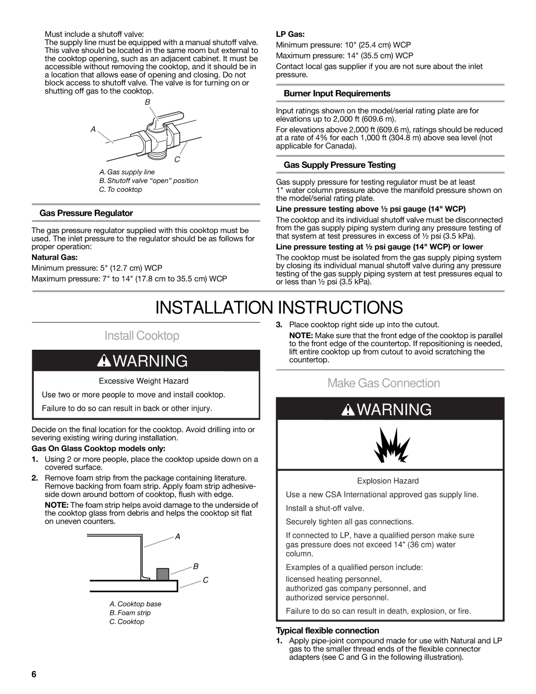
B
A
C
A. Gas supply line
B. Shutoff valve “open” position
C. To cooktop
Gas Pressure Regulator
The gas pressure regulator supplied with this cooktop must be used. The inlet pressure to the regulator should be as follows for proper operation:
Natural Gas:
Minimum pressure: 5" (12.7 cm) WCP
Maximum pressure: 7" to 14" (17.8 cm to 35.5 cm) WCP
LP Gas:
Minimum pressure: 10" (25.4 cm) WCP
Maximum pressure: 14" (35.5 cm) WCP
Contact local gas supplier if you are not sure about the inlet pressure.
Burner Input Requirements
Input ratings shown on the model/serial rating plate are for elevations up to 2,000 ft (609.6 m).
For elevations above 2,000 ft (609.6 m), ratings should be reduced at a rate of 4% for each 1,000 ft (304.8 m) above sea level (not applicable for Canada).
Gas Supply Pressure Testing
Gas supply pressure for testing regulator must be at least
1" water column pressure above the manifold pressure shown on the model/serial rating plate.
Line pressure testing above ½ psi gauge (14" WCP)
The cooktop and its individual shutoff valve must be disconnected from the gas supply piping system during any pressure testing of that system at test pressures in excess of ½ psi (3.5 kPa).
Line pressure testing at ½ psi gauge (14" WCP) or lower
The cooktop must be isolated from the gas supply piping system by closing its individual manual shutoff valve during any pressure testing of the gas supply piping system at test pressures equal to or less than ½ psi (3.5 kPa).
INSTALLATION INSTRUCTIONS
Install Cooktop
![]() WARNING
WARNING
Excessive Weight Hazard
Use two or more people to move and install cooktop. Failure to do so can result in back or other injury.
Decide on the final location for the cooktop. Avoid drilling into or severing existing wiring during installation.
Gas On Glass Cooktop models only:
1.Using 2 or more people, place the cooktop upside down on a covered surface.
2.Remove foam strip from the package containing literature. Remove backing from foam strip. Apply foam strip adhesive- side down around bottom of cooktop, flush with edge.
NOTE: The foam strip helps avoid damage to the underside of the cooktop glass from debris and helps the cooktop sit flat on uneven counters.
A
B
C
A. Cooktop base
B. Foam strip
C. Cooktop
3.Place cooktop right side up into the cutout.
NOTE: Make sure that the front edge of the cooktop is parallel to the front edge of the countertop. If repositioning is needed, lift entire cooktop up from cutout to avoid scratching the countertop.
Make Gas Connection
![]() WARNING
WARNING
Explosion Hazard
Use a new CSA International approved gas supply line.
Install a
Securely tighten all gas connections.
If connected to LP, have a qualified person make sure gas pressure does not exceed 14" (36 cm) water column.
Examples of a qualified person include:
licensed heating personnel,
authorized gas company personnel, and authorized service personnel.
Failure to do so can result in death, explosion, or fire.
Typical flexible connection
1.Apply
6