Location Requirements

WARNING

Explosion Hazard

Keep flammable materials and vapors, such as gasoline, away from refrigerator.

Failure to do so can result in death, explosion, or fire.

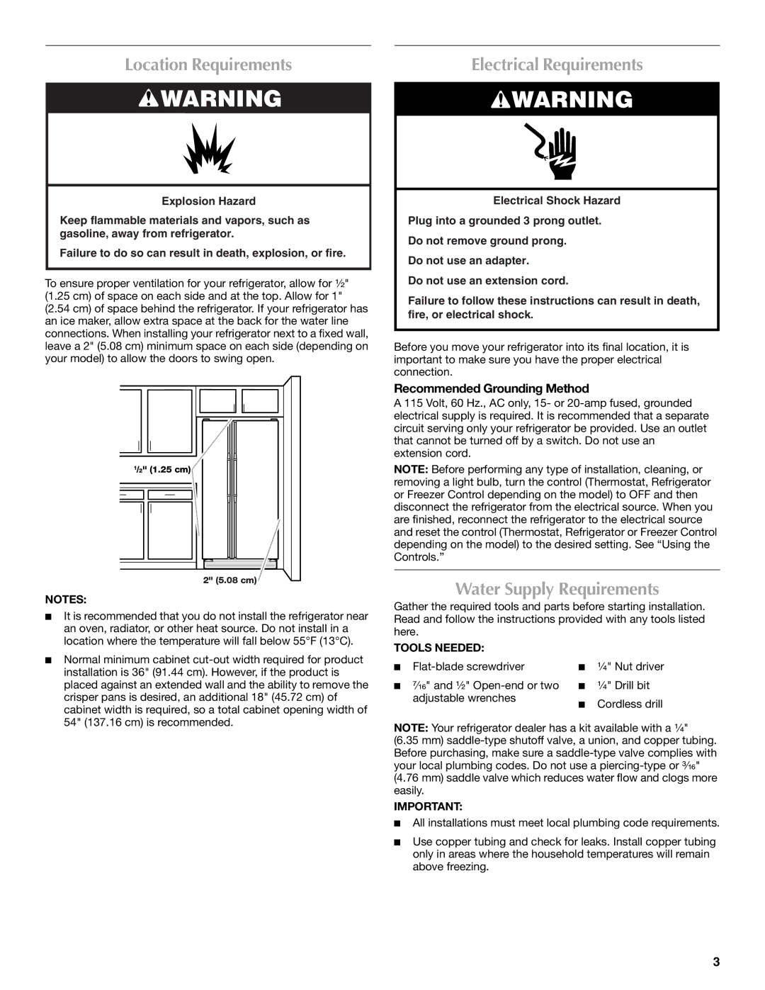
To ensure proper ventilation for your refrigerator, allow for ¹⁄₂" (1.25 cm) of space on each side and at the top. Allow for 1"

(2.54 cm) of space behind the refrigerator. If your refrigerator has an ice maker, allow extra space at the back for the water line connections. When installing your refrigerator next to a fixed wall, leave a 2" (5.08 cm) minimum space on each side (depending on your model) to allow the doors to swing open.

1/2" (1.25 cm)

2" (5.08 cm)

NOTES:

It is recommended that you do not install the refrigerator near an oven, radiator, or other heat source. Do not install in a location where the temperature will fall below 55°F (13°C).

Normal minimum cabinet cut-out width required for product installation is 36" (91.44 cm). However, if the product is placed against an extended wall and the ability to remove the crisper pans is desired, an additional 18" (45.72 cm) of cabinet width is required, so a total cabinet opening width of 54" (137.16 cm) is recommended.

Electrical Requirements

WARNING

Electrical Shock Hazard

Plug into a grounded 3 prong outlet.

Do not remove ground prong.

Do not use an adapter.

Do not use an extension cord.

Failure to follow these instructions can result in death, fire, or electrical shock.

Before you move your refrigerator into its final location, it is important to make sure you have the proper electrical connection.

Recommended Grounding Method

A 115 Volt, 60 Hz., AC only, 15- or 20-amp fused, grounded electrical supply is required. It is recommended that a separate circuit serving only your refrigerator be provided. Use an outlet that cannot be turned off by a switch. Do not use an extension cord.

NOTE: Before performing any type of installation, cleaning, or removing a light bulb, turn the control (Thermostat, Refrigerator or Freezer Control depending on the model) to OFF and then disconnect the refrigerator from the electrical source. When you are finished, reconnect the refrigerator to the electrical source and reset the control (Thermostat, Refrigerator or Freezer Control depending on the model) to the desired setting. See “Using the Controls.”

Water Supply Requirements

Gather the required tools and parts before starting installation. Read and follow the instructions provided with any tools listed here.

TOOLS NEEDED:

Flat-blade screwdriver

¹⁄₄" Nut driver

⁷⁄₁₆" and ¹⁄₂" Open-end or two

¹⁄₄" Drill bit


adjustable wrenches

Cordless drill


NOTE: Your refrigerator dealer has a kit available with a ¹⁄₄"

(6.35 mm) saddle-type shutoff valve, a union, and copper tubing. Before purchasing, make sure a saddle-type valve complies with your local plumbing codes. Do not use a piercing-type or ³⁄₁₆"

(4.76 mm) saddle valve which reduces water flow and clogs more easily.

IMPORTANT:

All installations must meet local plumbing code requirements.

Use copper tubing and check for leaks. Install copper tubing only in areas where the household temperatures will remain above freezing.

3

Page 3
Image 3
Maytag W10289680A Location Requirements, Electrical Requirements, Water Supply Requirements, Recommended Grounding Method

W10289680A, W10289681A specifications

Maytag, renowned for its durable and high-performance appliances, continues to innovate with the release of its key components, the W10289681A and W10289680A. These parts are designed specifically for Maytag washers and dryers, enhancing functionality and efficiency.

The W10289681A is a water inlet valve that plays a crucial role in controlling the flow of water into your washing machine. By utilizing advanced technology, it ensures accurate water levels for optimal washing performance. This part is designed with a high-strength construction to withstand wear and tear, ensuring longevity and reliability. The valve also features a dual inlet design, allowing both hot and cold water to flow into the machine, facilitating versatile washing cycles tailored to different fabric types and soiling levels.

The W10289680A, on the other hand, is a crucial part of the dryer system, specifically the thermal fuse. It serves as a safety feature that prevents the dryer from overheating, thereby protecting both the appliance and your home. When the internal temperature exceeds a predetermined limit, the thermal fuse disconnects the power, effectively shutting down the machine and preventing potential hazards. This safety mechanism is integral in prolonging the life of the dryer and ensuring safe operation.

Both components exemplify Maytag's commitment to quality and customer satisfaction. They are easy to install, making them user-friendly options for DIY repairs. Furthermore, these parts adhere to stringent industry standards, ensuring compatibility with a variety of Maytag washer and dryer models.

In addition to their individual functions, these components work in harmony to enhance the overall performance of the laundry system. The effective water control and safety features provided by the W10289681A and W10289680A ensure that laundry can be done efficiently and safely, reflecting the modern demands of household chores.

Overall, investing in Maytag parts like the W10289681A and W10289680A not only ensures the functionality of your appliances but also promotes a hassle-free laundry experience. With a focus on innovation, safety, and durability, Maytag solidifies its reputation as a leading brand in home appliances.