Exhaust hoods:
■■ Must be at least 12" (305 mm) from ground or any object that may obstruct exhaust (such as flowers, rocks, bushes, or snow).
Recommended Styles:
|
|
|
Louvered Hood |
| Box Hood |
Acceptable Style:
Angled Hood
Elbows:
■■ 45° elbows provide better airflow than 90° elbows.
Recommended Styles:
Good ![]() Better
Better ![]()
Clamps:
■■ Use clamps to seal all joints.
■■ Exhaust vent must not be connected or secured with screws
or other fastening devices that extend into interior of duct and catch lint. Do not use duct tape.
PLAN VENT SYSTEM
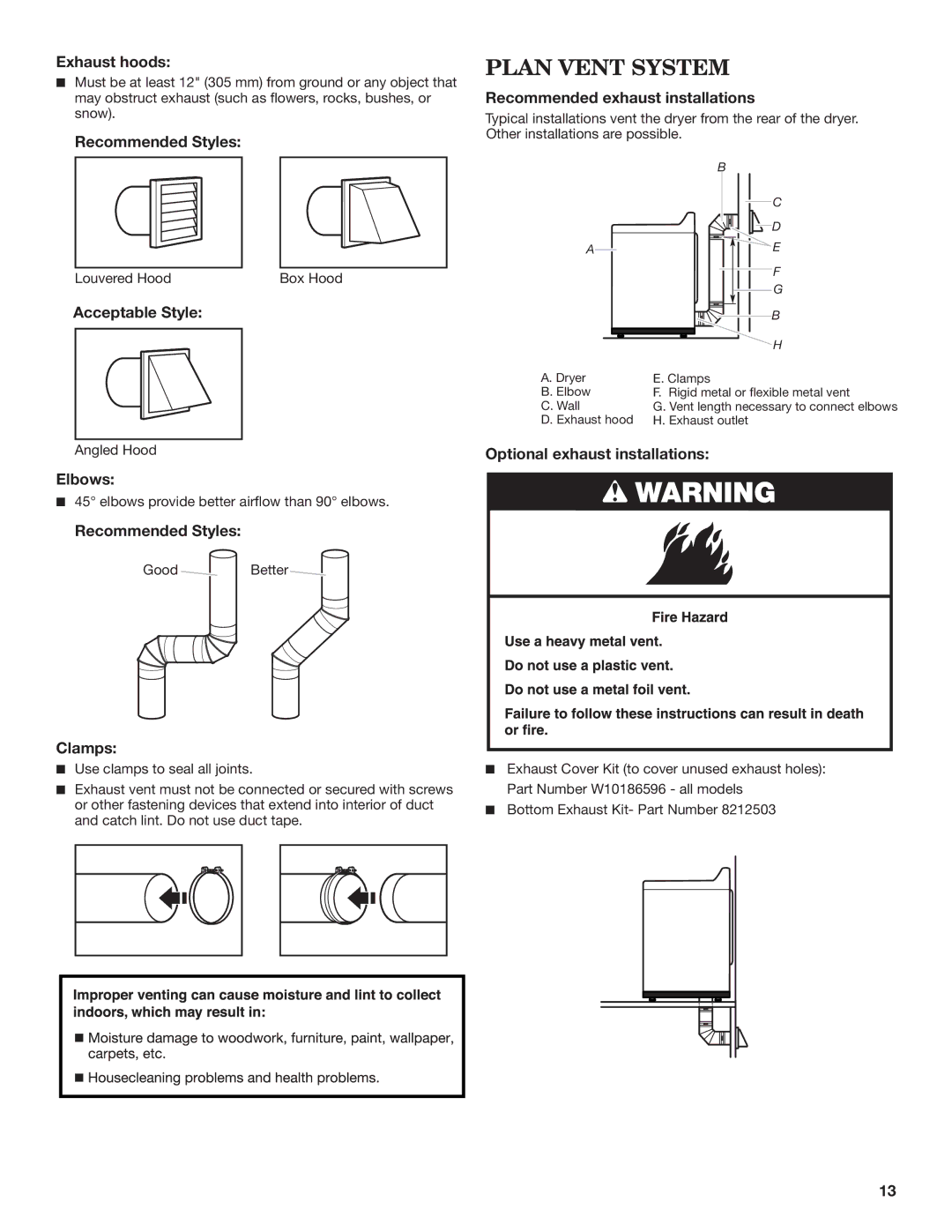
Recommended exhaust installations
Typical installations vent the dryer from the rear of the dryer. Other installations are possible.
| B |
| C |
| D |
A | E |
| F |
| G |
| B |
| H |
A. Dryer | E. Clamps |
B. Elbow | F. Rigid metal or flexible metal vent |
C. Wall | G. Vent length necessary to connect elbows |
D. Exhaust hood | H. Exhaust outlet |
Optional exhaust installations:
■■ Exhaust Cover Kit (to cover unused exhaust holes): Part Number W10186596 - all models
■■ Bottom Exhaust Kit- Part Number 8212503
13