OPERATION
CROSSOVER
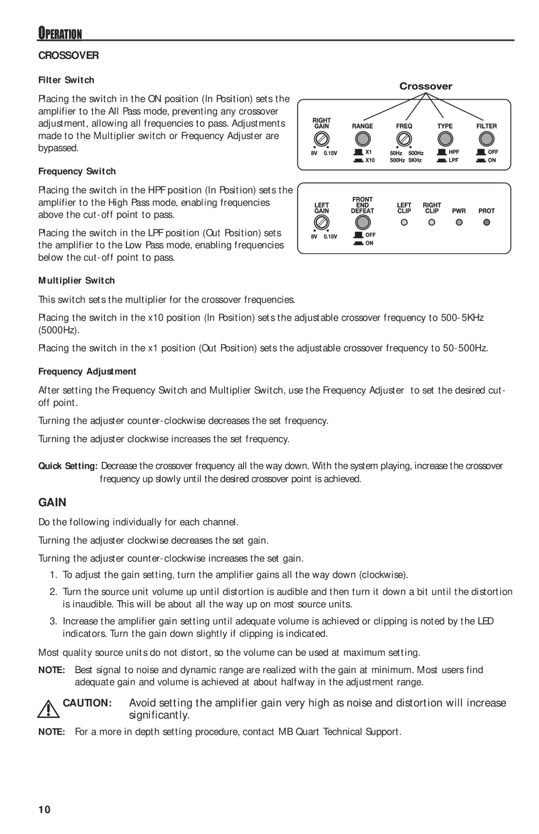
Filter Switch
Placing the switch in the ON position (In Position) sets the amplifier to the All Pass mode, preventing any crossover adjustment, allowing all frequencies to pass. Adjustments made to the Multiplier switch or Frequency Adjuster are bypassed.
Frequency Switch
Placing the switch in the HPF position (In Position) sets the amplifier to the High Pass mode, enabling frequencies above the
Placing the switch in the LPF position (Out Position) sets the amplifier to the Low Pass mode, enabling frequencies below the
Multiplier Switch
This switch sets the multiplier for the crossover frequencies.
Placing the switch in the x10 position (In Position) sets the adjustable crossover frequency to
Placing the switch in the x1 position (Out Position) sets the adjustable crossover frequency to
Frequency Adjustment
After setting the Frequency Switch and Multiplier Switch, use the Frequency Adjuster to set the desired cut- off point.
Turning the adjuster
Turning the adjuster clockwise increases the set frequency.
Quick Setting: Decrease the crossover frequency all the way down. With the system playing, increase the crossover frequency up slowly until the desired crossover point is achieved.
GAIN
Do the following individually for each channel.
Turning the adjuster clockwise decreases the set gain.
Turning the adjuster
1.To adjust the gain setting, turn the amplifier gains all the way down (clockwise).
2.Turn the source unit volume up until distortion is audible and then turn it down a bit until the distortion is inaudible. This will be about all the way up on most source units.
3.Increase the amplifier gain setting until adequate volume is achieved or clipping is noted by the LED indicators. Turn the gain down slightly if clipping is indicated.
Most quality source units do not distort, so the volume can be used at maximum setting.
NOTE: Best signal to noise and dynamic range are realized with the gain at minimum. Most users find adequate gain and volume is achieved at about halfway in the adjustment range.
CAUTION: Avoid setting the amplifier gain very high as noise and distortion will increase significantly.
NOTE: For a more in depth setting procedure, contact MB Quart Technical Support.
10
