Introduction
McIntosh Acoustic Engineers have refined the Loud- speaker System concept to provide superior sound quality in a versatile enclosure with five different installation methods.
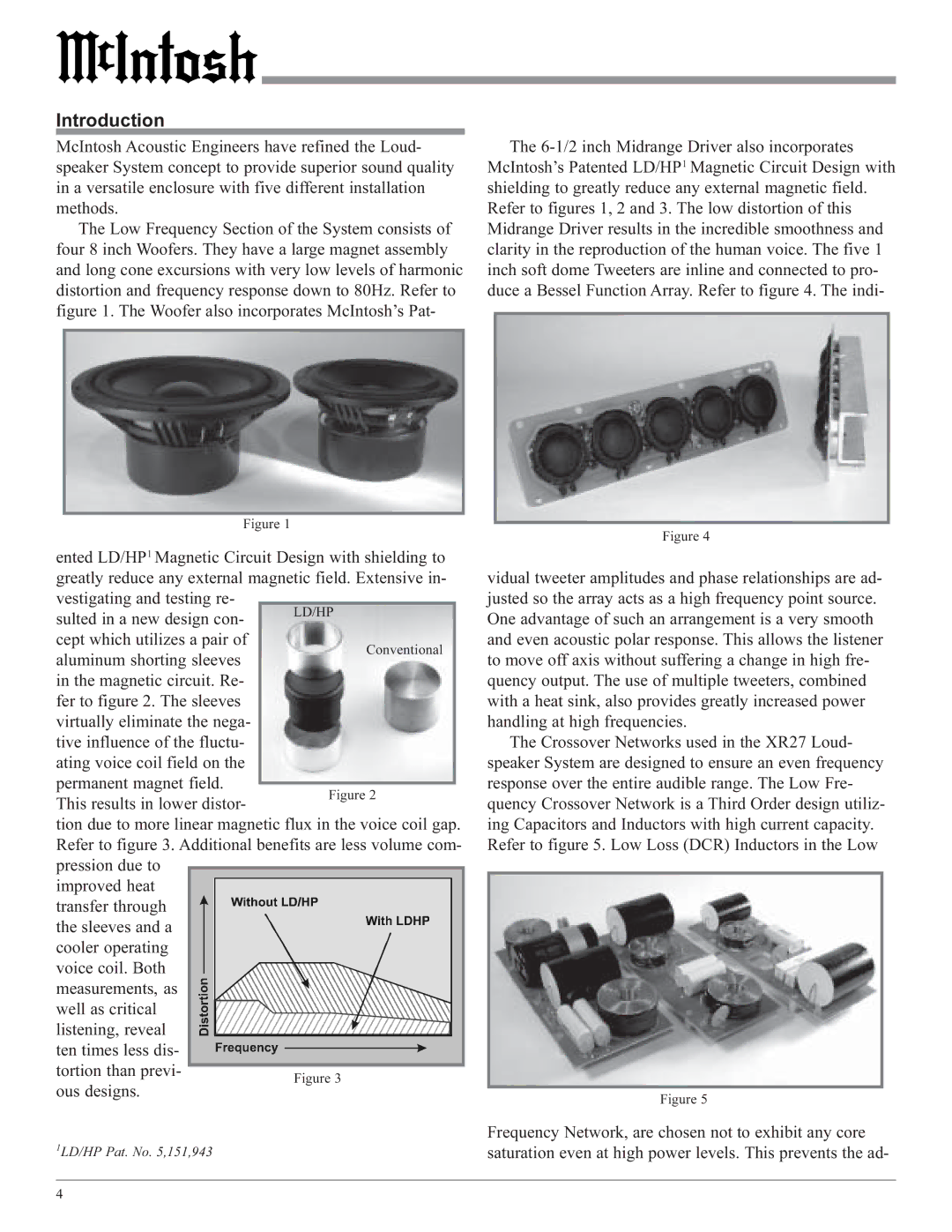
The Low Frequency Section of the System consists of four 8 inch Woofers. They have a large magnet assembly and long cone excursions with very low levels of harmonic distortion and frequency response down to 80Hz. Refer to figure 1. The Woofer also incorporates McIntosh’s Pat-
Figure 1
ented LD/HP1 Magnetic Circuit Design with shielding to
greatly reduce any external magnetic field. Extensive in- | ||
vestigating and testing re- |
| |
sulted in a new design con- | LD/HP | |
| ||
cept which utilizes a pair of | Conventional | |
aluminum shorting sleeves | ||
| ||
in the magnetic circuit. Re- |
| |
fer to figure 2. The sleeves |
| |
virtually eliminate the nega- |
| |
tive influence of the fluctu- |
| |
ating voice coil field on the |
| |
permanent magnet field. |
| |
| ||
The
Figure 4
vidual tweeter amplitudes and phase relationships are ad- justed so the array acts as a high frequency point source. One advantage of such an arrangement is a very smooth and even acoustic polar response. This allows the listener to move off axis without suffering a change in high fre- quency output. The use of multiple tweeters, combined with a heat sink, also provides greatly increased power handling at high frequencies.
The Crossover Networks used in the XR27 Loud- speaker System are designed to ensure an even frequency response over the entire audible range. The Low Fre-
This results in lower distor-
Figure 2
quency Crossover Network is a Third Order design utiliz-
tion due to more linear magnetic flux in the voice coil gap. Refer to figure 3. Additional benefits are less volume com- pression due to ![]() improved heat
improved heat
transfer through the sleeves and a
cooler operating voice coil. Both measurements, as
well as critical listening, reveal ten times less dis- tortion than previ-
ous designs.
1LD/HP Pat. No. 5,151,943
ing Capacitors and Inductors with high current capacity. Refer to figure 5. Low Loss (DCR) Inductors in the Low
Figure 5
Frequency Network, are chosen not to exhibit any core saturation even at high power levels. This prevents the ad-
4