|
|
| Specifications | ||||
|
|
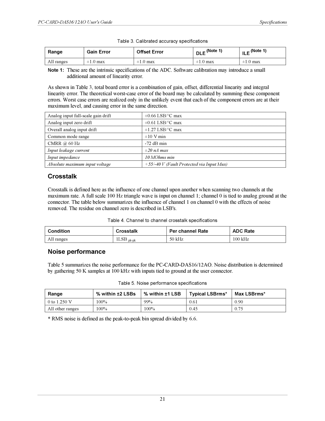
| Table 3. Calibrated accuracy specifications |
|
| ||
|
|
|
|
|
|
|
|
| Range | Gain Error |
| Offset Error | DLE (Note 1) | ILE (Note 1) |
|
| All ranges | ±1.0 max |
| ±1.0 max | ±1.0 max | ±1.0 max |
|
Note 1: These are the intrinsic specifications of the ADC. Software calibration may introduce a small additional amount of linearity error.
As shown in Table 3, total board error is a combination of gain, offset, differential linearity and integral linearity error. The theoretical
Analog input | ±0.66 LSB/°C max |
Analog input zero drift | ±0.61 LSB/°C max |
Overall analog input drift | ±1.27 LSB/°C max |
Common mode range | ±10 V min |
CMRR @ 60 Hz | |
Input leakage current | ±20 nA max |
Input impedance | 10 MOhms min |
Absolute maximum input voltage |
Crosstalk
Crosstalk is defined here as the influence of one channel upon another when scanning two channels at the maximum rate. A full scale 100 Hz triangle wave is input on channel 1; channel 0 is tied to analog ground at the connector. The table below summarizes the influence of channel 1 on channel 0 with the effects of noise removed. The residue on channel zero is described in LSB's.
Table 4. Channel to channel crosstalk specifications
Condition | Crosstalk | Per channel Rate | ADC Rate |
|
|
|
|
All ranges | 1LSB | 50 kHz | 100 kHz |
Noise performance
Table 5 summarizes the noise performance for the
Table 5. Noise performance specifications
Range | % within ±2 LSBs | % within ±1 LSB | Typical LSBrms* | Max LSBrms* |
|
|
|
|
|
0 to 1.250 V | 100% | 99% | 0.61 | 0.90 |
All other ranges | 100% | 100% | 0.45 | 0.75 |
* RMS noise is defined as the
21