PCI-QUAD-AC5 User's Guide

Installing the PCI-QUAD-AC5

Connecting the board for I/O operations

Connectors, cables – main I/O connector

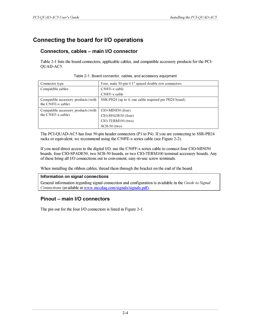
Table 2-1lists the board connectors, applicable cables, and compatible accessory products for the PCI- QUAD-AC5.

Table 2-1. Board connector, cables, and accessory equipment

Connector type

Four, male 50-pin 0.1" spaced double row connectors

Compatible cables

C50FE-x cable


C50FF-x cable

Compatible accessory products (with

SSR-PB24 (up to 4, one cable required per PB24 board)

the C50FE-x cable)


Compatible accessory products (with

CIO-MINI50 (four)

the C50FF-x cable)

CIO-SPADE50 (four)


CIO-TERM100 (two)


SCB-50 (two)

The PCI-QUAD-AC5 has four 50-pin header connectors (P1 to P4). If you are connecting to SSR-PB24 racks or equivalent, we recommend using the C50FE-x series cable (see Figure 2-2).

If you need direct access to the digital I/O, use the C50FF-x series cable to connect four CIO-MINI50 boards, four CIO-SPADE50, two SCB-50 boards, or two CIO-TERM100 terminal accessory boards. Any of these bring all I/O connections out to convenient, easy-to-use screw terminals.

When installing the ribbon cables, thread them through the bracket on the end of the board.

Information on signal connections

General information regarding signal connection and configuration is available in the Guide to Signal Connections (available at www.mccdaq.com/signals/signals.pdf).

Pinout – main I/O connectors

The pin out for the four I/O connectors is listed in Figure 2-1.
2-4

Page 13
Image 13
Measurement Specialties PCI-QUAD-AC5 manual Connecting the board for I/O operations, Connectors, cables main I/O connector