Measurement Specialties PCI-QUAD-AC5 Functional Details, Signal connections, 82C55 emulation

Models: PCI-QUAD-AC5

1 24
Download 24 pages 29.88 Kb
Page 17
Image 17

Chapter 4

Functional Details

Signal connections

All digital inputs and outputs on the PCI-QUAD-AC5 connector are TTL and are fully compatible with the inputs and outputs on the industry-standard PB-24 rack (Measurement Computing Corporation's model SSR-PB24).

82C55 emulation

The PCI-QUAD-AC5 board emulates the 82C55 chip. The 82C55 emulation initializes all ports as inputs on power-up and reset. A TTL input is a high impedance input. If you connect another TTL input device to the output, it could be turned on or off every time the board is reset.

To establish a consistent TTL level at power-up, use resistors tied to either +5V (pull-up) or ground (pull-down). There are open locations for pull-up and pull-down resistor SIPs on the board.

When an 82C55 emulation is powered on or reset, all pins are set to high-impedance input. Based on standard TTL functionality, these inputs will typically float high, and may have enough drive current to turn on external devices.

Consequently, if you have output devices such as solid state relays, they may be switched on whenever the computer is powered on or reset. To prevent unwanted switching, and to drive all outputs to a known state after power on or reset, pull all pins either high or low through a 2.2 K ohm resistor.

Pull-up and pull-down resistors

TTL inputs typically float high, but not reliably. The direction they float is dependent on the characteristics of the circuit and is unpredictable. If devices such as solid state relays are driven by digital I/O pins, they can be switched on whenever the computer is powered on or is reset. To prevent unwanted switching at power-on or reset, force all digital I/O pins to a known state by pulling all pins either high or low through a 2.2 K ohm resistor tied to either 5V or GND.

The pull-up resistor pulls the input to a high state (+5V) when the board is in input mode, as it would be on power-up or reset. A 2.2 K ohm resistor draws only 2 mA. A grounded 2.2 K ohm pull-down resistor pulls the I/O line low when the board is in input mode.

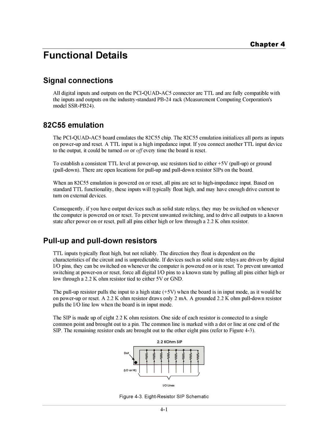
The SIP is made up of eight 2.2 K ohm resistors. One side of each resistor is connected to a single common point and brought out to a pin. The common line is marked with a dot or line at one end of the SIP. The remaining resistor ends are brought out to the other eight pins (refer to Figure 4-3).

2.2 KOhm SIP

Dot

(LO or HI)

I/O Lines

Figure 4-3. Eight-Resistor SIP Schematic

4-1

Page 17
Image 17
Measurement Specialties PCI-QUAD-AC5 manual Functional Details, Signal connections, 82C55 emulation