4. Overview
See page 2.
1 "Quick" clamping nut *
2 Support flange
3 Spindle
4 Spindle locking button
5 Sliding on/off switch *
6 Electronic signal indicator *
7 Speed adjustment wheel *
8
9 Trigger *
10 Additional handle / Additional handle with vibration damping *
11 Safety cover
12 Clamping nut *
13
14 Lever for safety guard attachment
* depending on equipment/not in scope of delivery
5. Commissioning
Before plugging in, check to see that the rated mains voltage and mains frequency,
as stated on the rating label, match your power supply.
5.1Attaching the additional handle
Always work with the additional handle attached (10)! Attach the additional handle
on the left or right of the machine and secure.
5.2Install safety guard
For safety reasons, always use the safety guard provided for the respective wheel! See
also chapter 10.
Safety guard for grinding
Designed for work with roughing wheels, flap sanding pads, diamond
See page 2, illustration G.
-Push and hold the lever (14). Place the safety guard (11) in the position indicated.
-Release the lever and turn the safety guard until the lever engages.
-Push the lever and turn the safety guard until the closed section is facing the operator.
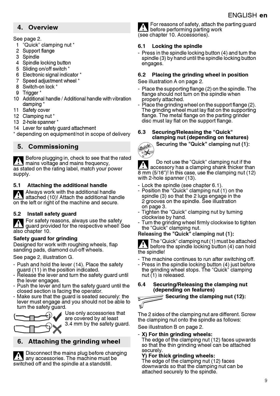
-Make sure that the guard is seated securely: the lever must engage and you should not be able to turn the safety guard.
Use only accessories that are covered by at least
3.4mm by the safety guard.
6. Attaching the grinding wheel
Disconnect the mains plug before changing any accessories. The machine must be
switched off and the spindle at a standstill.
ENGLISH en
For reasons of safety, attach the parting guard before performing parting work
(see chapter 10. Accessories).
6.1Locking the spindle
-Press in the spindle locking button (4) and turn the spindle (3) by hand until the spindle locking button engages.
6.2Placing the grinding wheel in position See illustration A on page 2.
-Place the supporting flange (2) on the spindle. The flange should not turn on the spindle when properly attached.
-Place the grinding wheel on the support flange (2). The grinding wheel must lay flat on the supporting flange. The metal flange on the parting grinder disc must lay flat on the support flange.
6.3Securing/Releasing the "Quick" clamping nut (depending on features)
Securing the "Quick" clamping nut (1):
Do not use the "Quick" clamping nut if the accessory has a clamping shank thicker than
8 mm (5/16“)! In this case, use the clamping nut (12) with
- Lock the spindle (see chapter 6.1).
- Position the "Quick" clamping nut (1) on the spindle (3) so that the 2 lugs engage in the 2 grooves on the spindle. See illustration on page 3.
- Tighten the "Quick" clamping nut by turning clockwise by hand.
- Turn the grinding wheel firmly clockwise to tighten the "Quick" clamping nut.
Releasing the "Quick" clamping nut (1):
The "Quick" clamping nut (1) must be attached before the spindle locking button (4) can hold
the spindle!
-The machine continues to run after switching off.
-Press in the spindle locking button (4) just before the grinding wheel stops. The "Quick" clamping nut (1) is released.
6.4Securing/Releasing the clamping nut (depending on features)
![]() Securing the clamping nut (12):
Securing the clamping nut (12):
The 2 sides of the clamping nut are different. Screw the clamping nut onto the spindle as follows:
See illustration B on page 2.
- X) For thin grinding wheels:
The edge of the clamping nut (12) faces upwards so that the thin grinding wheel can be attached securely.
Y) For thick grinding wheels:
The edge of the clamping nut (12) faces downwards so that the clamping nut can be attached securely to the spindle.
9