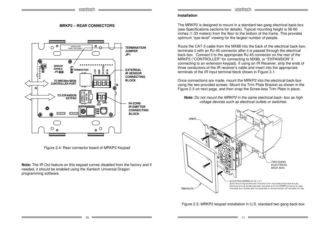
MRKP2 specifications
The Xantech MRKP2 is a state-of-the-art multi-channel audio distribution system designed to enhance both residential and commercial audio systems. This innovative product stands out due to its impressive array of features, advanced technologies, and user-friendly characteristics that cater to the needs of audiophiles and casual listeners alike.At the core of the MRKP2's functionality is its ability to distribute high-quality audio across multiple zones. With support for up to eight individual zones, users can enjoy synchronized audio or personalize listening experiences in different areas of the home or office. The system accommodates various audio sources, ensuring flexibility and convenience in playback options. Whether it’s streaming music, playing CDs, or connecting through various digital inputs, the MRKP2 supports it all, providing endless entertainment possibilities.
One of the key features of the Xantech MRKP2 is its compatibility with both traditional wired connections and modern wireless technologies. This dual functionality allows users to integrate the system seamlessly with existing setups. The MRKP2 also incorporates built-in power amplifiers, each capable of delivering high-quality sound without the need for additional equipment, streamlining installation and reducing clutter.
Control of the MRKP2 is intuitive, thanks to its user-friendly interface. The device can be managed via physical keypads distributed throughout the zones, or remotely using smartphone applications, enabling users to adjust settings effortlessly. Additionally, the MRKP2 is compatible with popular home automation systems, allowing for integrated control through a central hub.
The MRKP2’s audio quality is underpinned by advanced digital signal processing (DSP) technology. This ensures that sound is not only distributed efficiently but also remains true to its original quality. The system features multiple EQ settings, giving users the ability to customize their audio experience according to their preferences and room acoustics.
In terms of reliability, the Xantech MRKP2 is designed to endure. Constructed with high-quality materials and advanced engineering techniques, it promises longevity and robust performance under various conditions. Its compact design allows for easy integration into different environments without occupying excessive space.
Overall, the Xantech MRKP2 is an exemplary choice for anyone looking to upgrade their audio distribution system. Its combination of zoned audio flexibility, cutting-edge technology, and user-centric features make it a remarkable solution for modern audio needs, ensuring that every space can be turned into an immersive listening environment.

