Metrologic Instruments MLPN 2159 manual Parts of the Scanner, Code has been decoded

Models: MLPN 2159

1 28
Download 28 pages 5.19 Kb
Page 9
Image 9

Parts of the Scanner

1Green and

Red LEDs

3 Laser Output Window

2 Speaker

4 Mil spec Connector
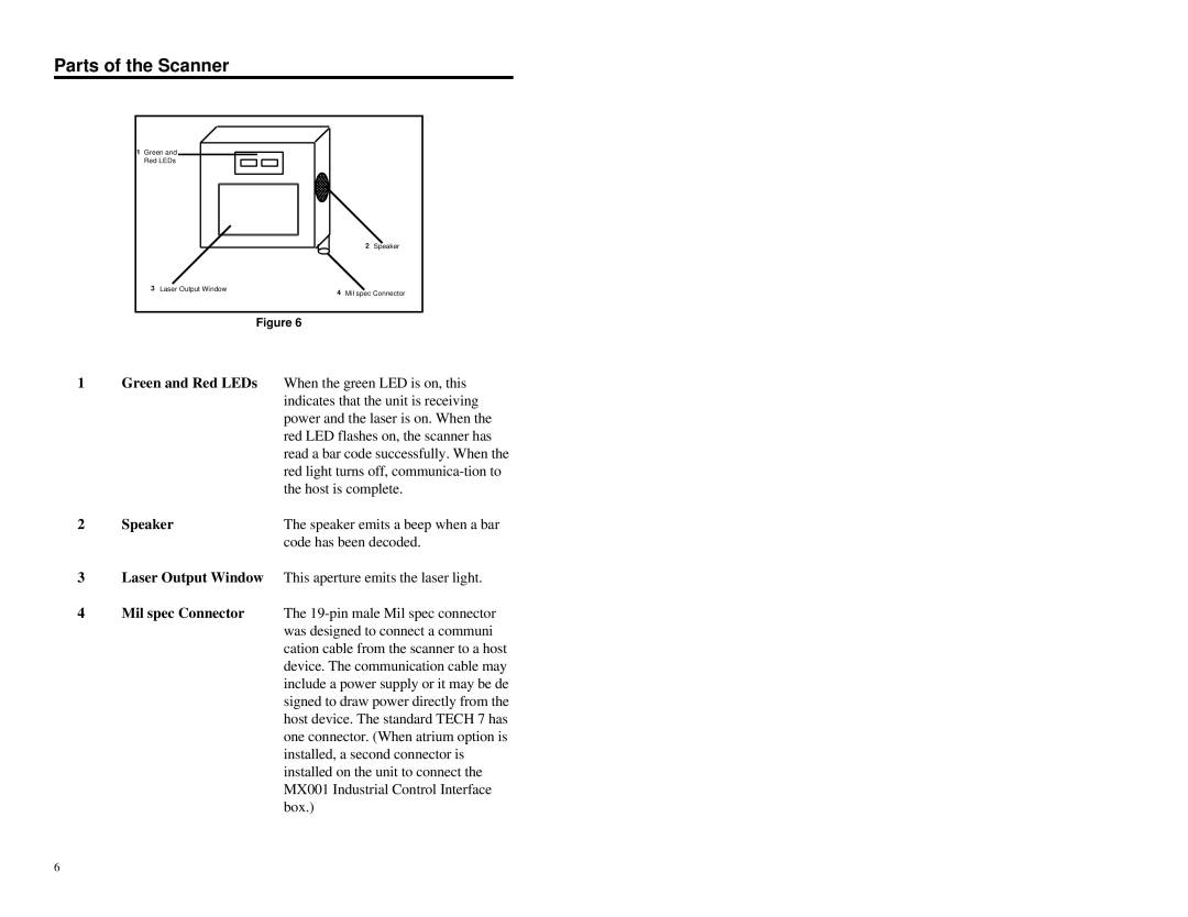
Figure 6

1Green and Red LEDs When the green LED is on, this indicates that the unit is receiving power and the laser is on. When the red LED flashes on, the scanner has read a bar code successfully. When the red light turns off, communica-tion to the host is complete.

2

Speaker

The speaker emits a beep when a bar


code has been decoded.

3Laser Output Window This aperture emits the laser light.

4Mil spec Connector The 19-pin male Mil spec connector was designed to connect a communi cation cable from the scanner to a host device. The communication cable may include a power supply or it may be de signed to draw power directly from the host device. The standard TECH 7 has one connector. (When atrium option is installed, a second connector is installed on the unit to connect the MX001 Industrial Control Interface box.)

6

Page 9
Image 9
Metrologic Instruments MLPN 2159 manual Parts of the Scanner, Code has been decoded