PRE-OPERATION
GENERAL
Whenever adjusting, cleaning, lubricating or otherwise servicing this forage box, you must shutoff and lockout power to the box. Because this box can be truck mounted or powered by a tractor, methods vary. On truck mounted units, the connection between the PTO and box is permanently installed and not intended to be disconnected. On trucks, disengage the PTO drive, turn off the engine, set the parking brake, remove the ignition keys and keep them in your possession to prevent any- one else from accidentally applying power to the box un- expectedly. For tractors, disengage the hydraulics, turn off the engine, set the brakes.
Throughout this manual, when directed to shutoff and lockout power, be familiar with the previously described procedures for the type of machine you are operating.
Be sure your forage box is properly mounted to the truck frame or to the wagon running gear. Consult your dealer if you have any questions about proper installation. A tie down kit from the manufacturer and illustrated in the parts listing of this manual is available for wagon applica- tions.
Hydraulic input to the 9100 forage box requires 35GPM
@3000 PSI. If truck mounted, install a relief valve set at 3000 PSI. Engine RPM should be 1500 RPM. Set up hy- draulic system on truck mounted units with a 40 gallon reservoir minimum. Call factory for further information.
WARNING: INSPECT REGULARLY THAT ALL CONNECTIONS AND BOLTS ARE TIGHT AND SE- CURE BEFORE OPERATING. FAILURE TO HEED MAY RESULT IN SERIOUS PERSONAL INJURY OR DEATH.
Inspect the forage box for proper adjustments as this will ensure maximum machine performance. See “Adjust- ments” section. Grease and oil the forage box as re- quired. See “Lubrication” section.
Depending on make and model of truck, it may be neces- sary to install a light converter. (Meyer part
AIR BRAKE HOOKUP
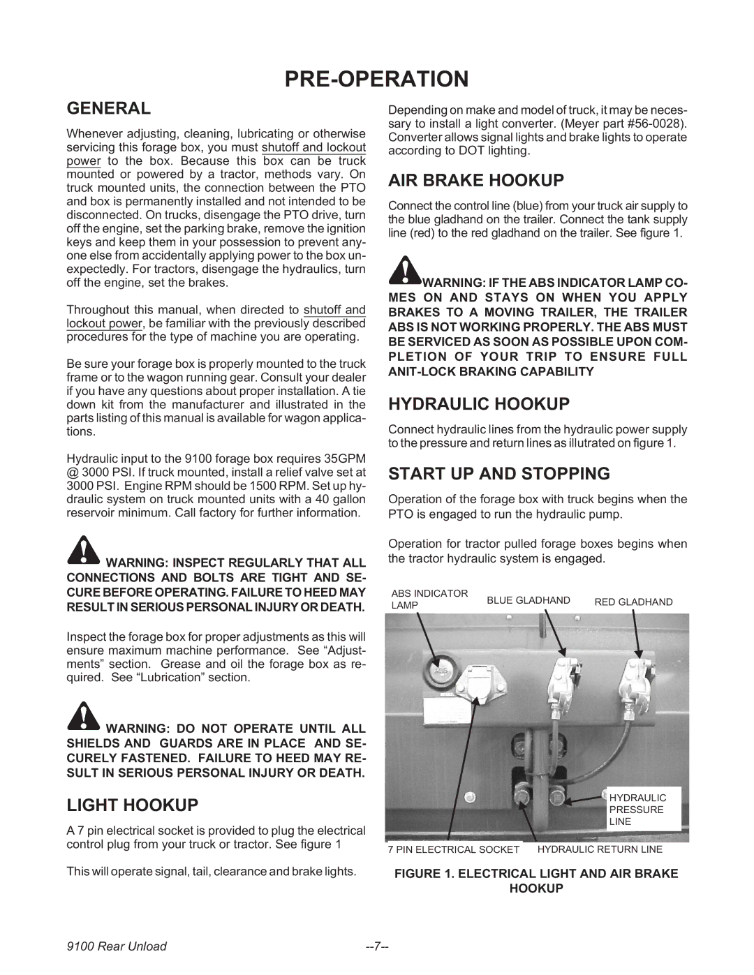
Connect the control line (blue) from your truck air supply to the blue gladhand on the trailer. Connect the tank supply line (red) to the red gladhand on the trailer. See figure 1.
WARNING: IF THE ABS INDICATOR LAMP CO- MES ON AND STAYS ON WHEN YOU APPLY BRAKES TO A MOVING TRAILER, THE TRAILER ABS IS NOT WORKING PROPERLY. THE ABS MUST BE SERVICED AS SOON AS POSSIBLE UPON COM- PLETION OF YOUR TRIP TO ENSURE FULL
HYDRAULIC HOOKUP
Connect hydraulic lines from the hydraulic power supply to the pressure and return lines as illutrated on figure 1.
START UP AND STOPPING
Operation of the forage box with truck begins when the PTO is engaged to run the hydraulic pump.
Operation for tractor pulled forage boxes begins when the tractor hydraulic system is engaged.
ABS INDICATOR | BLUE GLADHAND | RED GLADHAND | |
LAMP | |||
|
|
WARNING: DO NOT OPERATE UNTIL ALL SHIELDS AND GUARDS ARE IN PLACE AND SE- CURELY FASTENED. FAILURE TO HEED MAY RE- SULT IN SERIOUS PERSONAL INJURY OR DEATH.
LIGHT HOOKUP
A 7 pin electrical socket is provided to plug the electrical control plug from your truck or tractor. See figure 1
This will operate signal, tail, clearance and brake lights.
HYDRAULIC
PRESSURE
LINE
7 PIN ELECTRICAL SOCKET HYDRAULIC RETURN LINE
FIGURE 1. ELECTRICAL LIGHT AND AIR BRAKE
HOOKUP
9100 Rear Unload |