Manuals
/
MHP
/
Household Appliance
/
Indoor Fireplace
MHP
EWF36A Ceiling Chimney Hole Possible Obstructions, Cutting the Hole, Framing the Ceiling Hole
Models:
EWF36A
1
10
32
32
Download
32 pages
17.58 Kb
7
8
9
10
11
12
13
14
Page 10
Image 10
Page 9
Page 11
Page 10
Image 10
Page 9
Page 11
Contents
Homeowner’s Installation and Operating Manual
EWF36A Fireplace
Do Not Discard This Manual: Retain for Future Use
Vermont Castings EWF36A
Table of Contents
Introduction
20005167
Description
Safety Information
Precautions
Drafts
EWF36A Woodburning Fireplace
Specifications
EWF36A
Vermont Castings EWF36A
Vermont Castings EWF36A
Chase Installation
20005167
Illustration Key
Chimney Requirements - Offset Installations
30˚ Elbow Offsets
Vermont Castings EWF36A
Planning the Chimney Run
Planning Information
Mounting the Fireplace
The Ten Foot Rule
Chimney Supports
Installation
Chase Installation
Insulating Fireplace Enclosure for Cold Climates
Framing
Straight-UpChimney Installation
Offset Installation
EB1 Receptacle Hookup
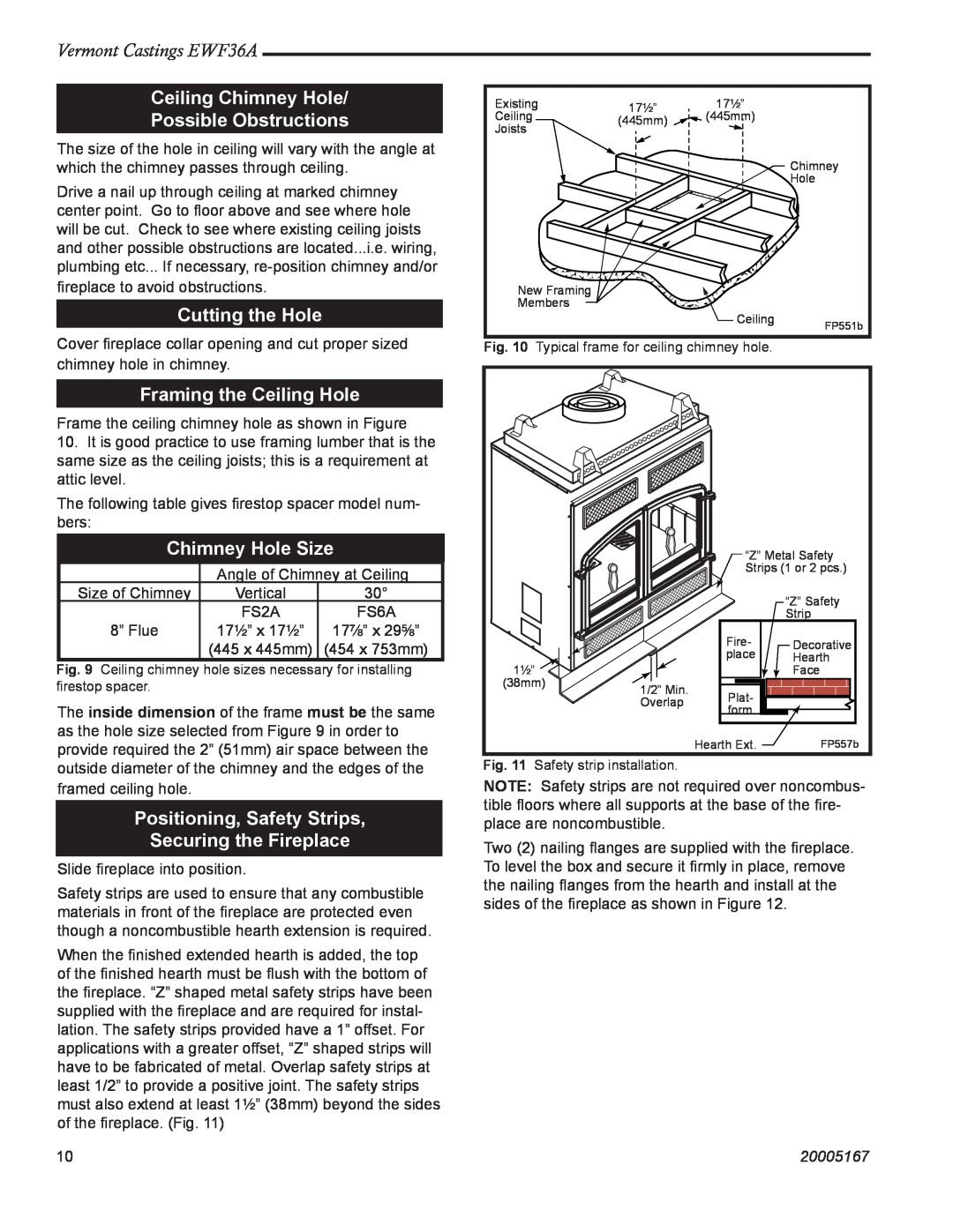
Cutting the Hole
Positioning, Safety Strips Securing the Fireplace
Ceiling Chimney Hole Possible Obstructions
Framing the Ceiling Hole
Installation Precautions
Installation Instructions
Installating Outside Air Kit
Vermont Castings EWF36A
Vermont Castings EWF36A
Installing the Chimney System
20005167
Continue Installing Pipe to Complete Run
Installing the Firestop Spacer
Proper Firestop Spacer Installation
in the Ceiling Hole
Installing Chimney in a Chase
Install Remainder of Chimney Sections
Install Top Housing or Termination
Penetrating the Roof
Side Wall Protection
Finish Wall
Mantels
Vermont Castings EWF36A
Vermont Castings EWF36A
Hearth Installation
COMMON MATERIALS AND FACTORS
20005167
Minimum Wall Clearances
Minimum Hearth Extension Dimensions
Vermont Castings EWF36A
20005167
EWF36A Controls
Operation
Attach Handles
Primary Air Control
Glass Doors
Use the Air Control Settings
The Fan
Burn Only High-QualityWood
Special Tactics for Cold-ClimateHeating
Starting and Maintaining a Wood Fire
Reloading and Reviving a Wood Fire
Vermont Castings EWF36A
Vermont Castings EWF36A
Remove and Store Ash Safely
20005167
Adjust the Door Latch Periodically
Maintenance
Cleaning the Glass
Inspection and Cleaning
How to Replace Gaskets
When to Suspect a Combustor Problem
Removing, Cleaning or Replacing the Combustor
Inspecting the Combustor
Replacing the Door Gaskets
A Clean Chimney System is Safer and Works Better
The Chimney System
Replace Damaged Door Glass Immediately
Vermont Castings EWF36A
Maintenance Schedule
Yearly Spring Cleaning
Fireplace Daily
Vermont Castings EWF36A
Chimney Components
20005167
20005167
EWF36A Fireplace
Vermont Castings EWF36A
Description
20005167
EWF36A Fireplace continued
Vermont Castings EWF36A
Description
Trim Kits
Optional Accessories
Fan Kit
Screen Kit
Vermont Castings EWF36A
20005167
Limited 3 Year Warranty
Warranty
20005167
MHSC
149 Cleveland Drive • Paris, Kentucky
Top
Page
Image
Contents