5.If it is necessary to add or remove conveyor links to achieve the correct tension, OR if it is necessary to reverse the conveyor belt for correct orientation, the belt will need to be removed from the conveyor frame. If this is necessary, perform the following procedure:

Remove the conveyor assembly from the oven and place it flat on the floor.

Remove the master links using long-nose pliers. Then, roll up the belt along the length of the conveyor frame.

Add or remove belt links as necessary to achieve the correct belt tension.

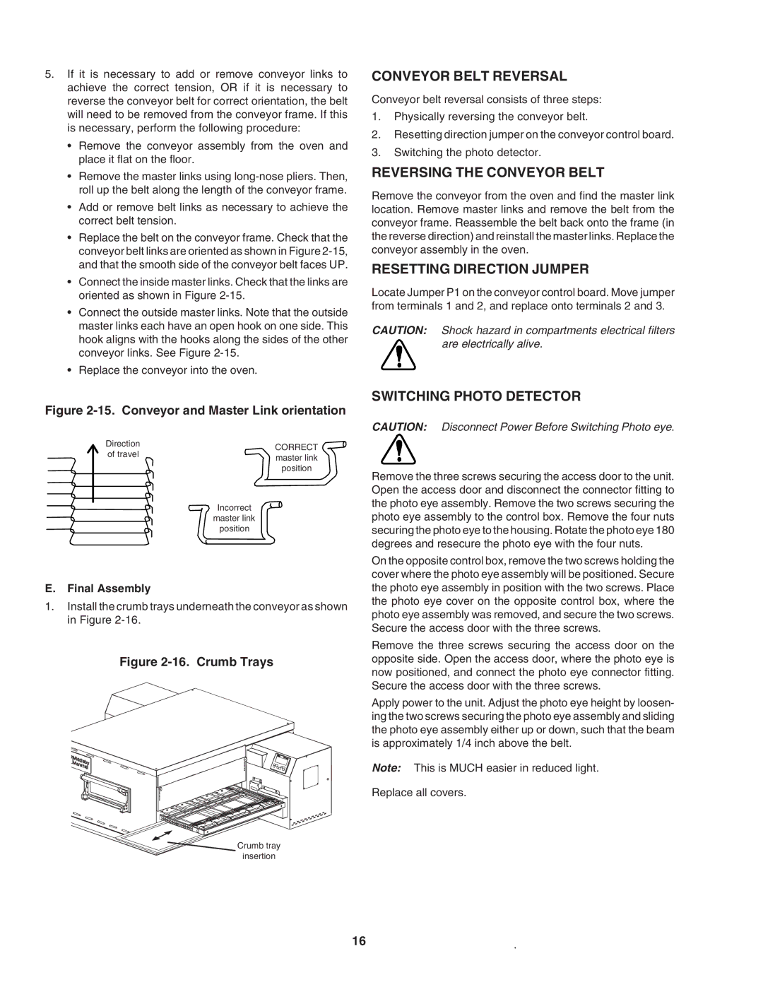
Replace the belt on the conveyor frame. Check that the conveyor belt links are oriented as shown in Figure 2-15, and that the smooth side of the conveyor belt faces UP.

Connect the inside master links. Check that the links are oriented as shown in Figure 2-15.

Connect the outside master links. Note that the outside master links each have an open hook on one side. This hook aligns with the hooks along the sides of the other conveyor links. See Figure 2-15.

Replace the conveyor into the oven.

Figure 2-15. Conveyor and Master Link orientation

Direction

CORRECT

of travel

master link


position

Incorrect master link position

E.Final Assembly

1.Install the crumb trays underneath the conveyor as shown in Figure 2-16.

Figure 2-16. Crumb Trays

Crumb tray

insertion

CONVEYOR BELT REVERSAL

Conveyor belt reversal consists of three steps:

1.Physically reversing the conveyor belt.

2.Resetting direction jumper on the conveyor control board.

3.Switching the photo detector.

REVERSING THE CONVEYOR BELT

Remove the conveyor from the oven and find the master link location. Remove master links and remove the belt from the conveyor frame. Reassemble the belt back onto the frame (in the reverse direction) and reinstall the master links. Replace the conveyor assembly in the oven.

RESETTING DIRECTION JUMPER

Locate Jumper P1 on the conveyor control board. Move jumper from terminals 1 and 2, and replace onto terminals 2 and 3.

CAUTION: Shock hazard in compartments electrical filters are electrically alive.

SWITCHING PHOTO DETECTOR

CAUTION: Disconnect Power Before Switching Photo eye.

Remove the three screws securing the access door to the unit. Open the access door and disconnect the connector fitting to the photo eye assembly. Remove the two screws securing the photo eye assembly to the control box. Remove the four nuts securing the photo eye to the housing. Rotate the photo eye 180 degrees and resecure the photo eye with the four nuts.

On the opposite control box, remove the two screws holding the cover where the photo eye assembly will be positioned. Secure the photo eye assembly in position with the two screws. Place the photo eye cover on the opposite control box, where the photo eye assembly was removed, and secure the two screws. Secure the access door with the three screws.

Remove the three screws securing the access door on the opposite side. Open the access door, where the photo eye is now positioned, and connect the photo eye connector fitting. Secure the access door with the three screws.

Apply power to the unit. Adjust the photo eye height by loosen- ing the two screws securing the photo eye assembly and sliding the photo eye assembly either up or down, such that the beam is approximately 1/4 inch above the belt.

Note: This is MUCH easier in reduced light.

Replace all covers.

16

Page 20
Image 20
Middleby Marshall PS740E Conveyor Belt Reversal, Reversing the Conveyor Belt, Resetting Direction Jumper, Final Assembly

PS740E specifications

The Middleby Marshall PS740E is a cutting-edge conveyor oven designed to provide exceptional baking performance, particularly in high-volume food service operations. This innovative piece of equipment is particularly favored by pizza restaurants, quick-service eateries, and other establishments that require reliable and consistent cooking results.

One of the standout features of the PS740E is its advanced cooking technology. Equipped with the patented "Jetlube" system, the oven utilizes high-velocity forced air that enhances heat transfer and ensures even cooking across the product. This technology not only cooks food quickly but also preserves the flavor and texture of items, making it a preferred choice for commercial kitchens focused on quality.

The PS740E is built with an energy-efficient design that promotes sustainability while reducing operational costs. It features an electronic control system that allows operators to easily manage cooking times and temperatures, thereby enhancing productivity without sacrificing food quality. With adjustable conveyor speeds and temperature controls that can reach up to 600°F, the oven provides versatility in cooking a variety of menu items, including pizzas, sandwiches, and baked goods.

Another notable characteristic of the Middleby Marshall PS740E is its durable construction. Designed for the rigors of commercial use, it features stainless steel exteriors, which not only present a professional appearance but also ensure easy cleaning and maintenance. The oven's high-quality components are engineered to withstand the demands of daily use, further reinforcing its reputation as a reliable workhorse in any kitchen.

The PS740E is also designed with user convenience in mind. It is compact yet capable of accommodating large volumes of food, thanks to its efficient conveyor system. This allows for streamlined workflow in busy environments, minimizing wait times and enhancing customer satisfaction.

In conclusion, the Middleby Marshall PS740E stands out in the market for its innovative cooking technologies, energy efficiency, durable design, and user-friendly features. It represents a smart investment for food service operators looking to enhance their menu offerings while maintaining efficiency in food preparation and cooking processes.