SECTION 5 − OPERATION
5-1. Controls
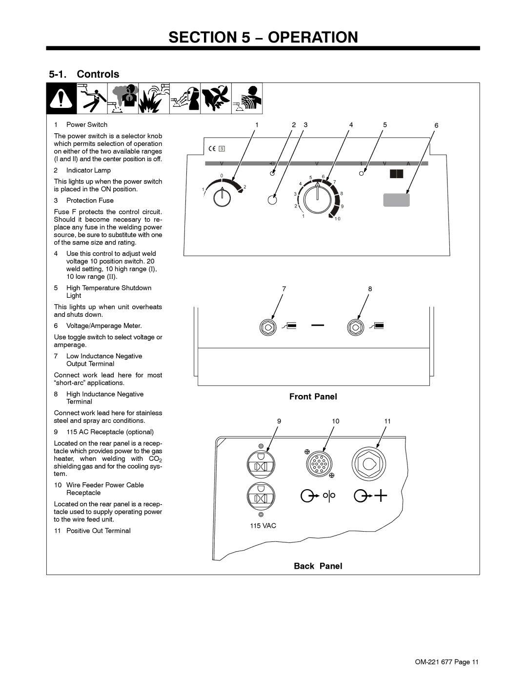
1 Power Switch | 1 | 2 3 | 4 | 5 | 6 |
The power switch is a selector knob which permits selection of operation on either of the two available ranges (I and II) and the center position is off.
2 Indicator Lamp
This lights up when the power switch is placed in the ON position.
3 Protection Fuse
Fuse F protects the control circuit. Should it become necesary to re- place any fuse in the welding power source, be sure to substitute with one of the same size and rating.
4Use this control to adjust weld voltage 10 position switch. 20 weld setting, 10 high range (I), 10 low range (II).
5High Temperature Shutdown Light
This lights up when unit overheats and shuts down.
6 Voltage/Amperage Meter.
Use toggle switch to select voltage or amperage.
7Low Inductance Negative Output Terminal
Connect work lead here for most
8High Inductance Negative Terminal
Connect work lead here for stainless steel and spray arc conditions.
9 115 AC Receptacle (optional)
Located on the rear panel is a recep- tacle which provides power to the gas heater, when welding with CO2 shielding gas and for the cooling sys- tem.
10Wire Feeder Power Cable Receptacle
Located on the rear panel is a recep- tacle used to supply operating power to the wire feed unit.
11 Positive Out Terminal
78
Front Panel
9 | 10 | 11 |
115 VAC