5-4. Program Push Button
1
2
Non-CE Models
Program
3
1
2
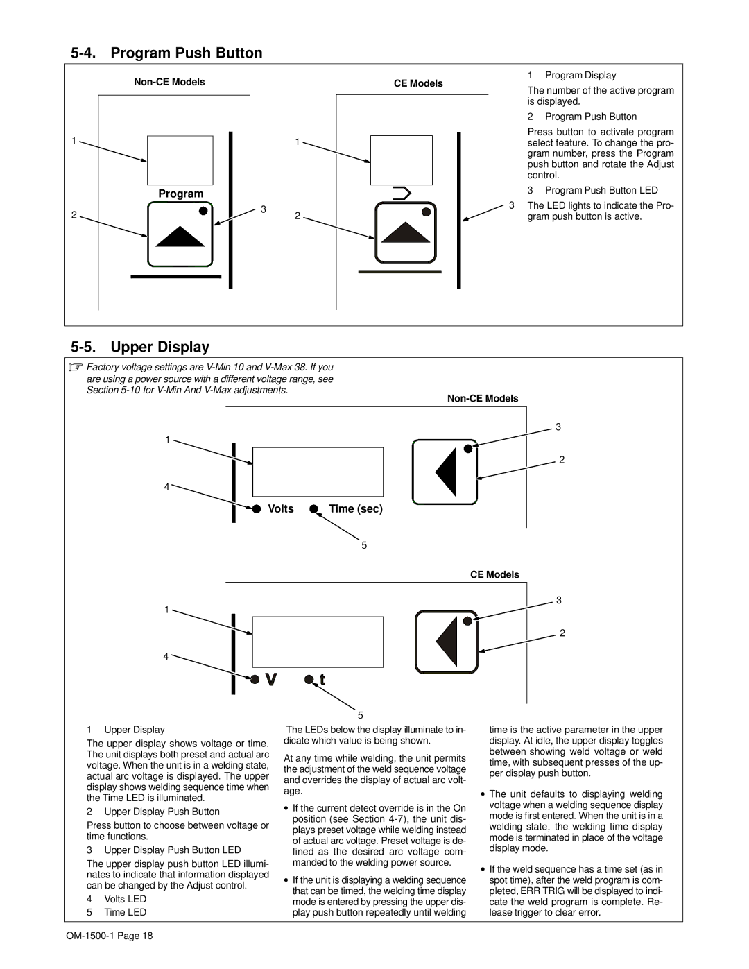
1 Program Display
CE Models
The number of the active program is displayed.
2 Program Push Button
Press button to activate program select feature. To change the pro- gram number, press the Program push button and rotate the Adjust control.
3 Program Push Button LED
3 The LED lights to indicate the Pro- gram push button is active.
5-5. Upper Display
.Factory voltage settings are
are using a power source with a different voltage range, see Section
1 |
|
4 |
|
Volts | Time (sec) |
| 5 |
CE Models
1
4
5
3
2
3
2
1 Upper Display
The upper display shows voltage or time. The unit displays both preset and actual arc voltage. When the unit is in a welding state, actual arc voltage is displayed. The upper display shows welding sequence time when the Time LED is illuminated.
2 Upper Display Push Button
Press button to choose between voltage or time functions.
3 Upper Display Push Button LED
The upper display push button LED illumi- nates to indicate that information displayed can be changed by the Adjust control.
4Volts LED
5Time LED
The LEDs below the display illuminate to in- dicate which value is being shown.
At any time while welding, the unit permits the adjustment of the weld sequence voltage and overrides the display of actual arc volt- age.
•If the current detect override is in the On position (see Section
•If the unit is displaying a welding sequence that can be timed, the welding time display mode is entered by pressing the upper dis- play push button repeatedly until welding
time is the active parameter in the upper display. At idle, the upper display toggles between showing weld voltage or weld time, with subsequent presses of the up- per display push button.
•The unit defaults to displaying welding voltage when a welding sequence display mode is first entered. When the unit is in a welding state, the welding time display mode is terminated in place of the voltage display mode.
•If the weld sequence has a time set (as in spot time), after the weld program is com- pleted, ERR TRIG will be displayed to indi- cate the weld program is complete. Re- lease trigger to clear error.