SECTION 3 – INTRODUCTION
3-1. Specifications
Type of Input | Welding Power | Wire Feed | Wire | Welding | IP | Overall |
| |
Diameter | Circuit | Weight | ||||||
Power | Source Type | Speed Range | Rating | Dimensions | ||||
Range | Rating |
| ||||||
|
|
|
|
|
| |||
|
|
|
|
|
|
|
| |
24 Volts AC | Constant Voltage (CV) | Standard: 50 To | .023 To 1/8 in | 100 Volts, | IP 21 | Length: 27 in | 58 lb | |
DC With | 780 ipm (1.3 To | (0.6 To 3.2 | 750 |
| (686 mm) | (26 kg) | ||
10 Amperes | Contactor Control | 19.8 mpm) | mm) | Amperes, |
| Width: |
| |
50/60 Hertz |
|
|
| 100% Duty |
|
| ||
|
|
|
| (318 mm) |
| |||
|
| Optional High | Max Spool | Cycle |
|
| ||
|
|
| Height: 14 in |
| ||||
|
| Speed: 90 To | Weight: 60 lb |
|
|
| ||
|
| 1440 ipm (2.3 To | (27 kg) |
|
| (356 mm) |
| |
|
| 36.6 mpm) |
|
|
|
|
| |
|
|
|
|
|
|
|
|
SECTION 4 – INSTALLATION
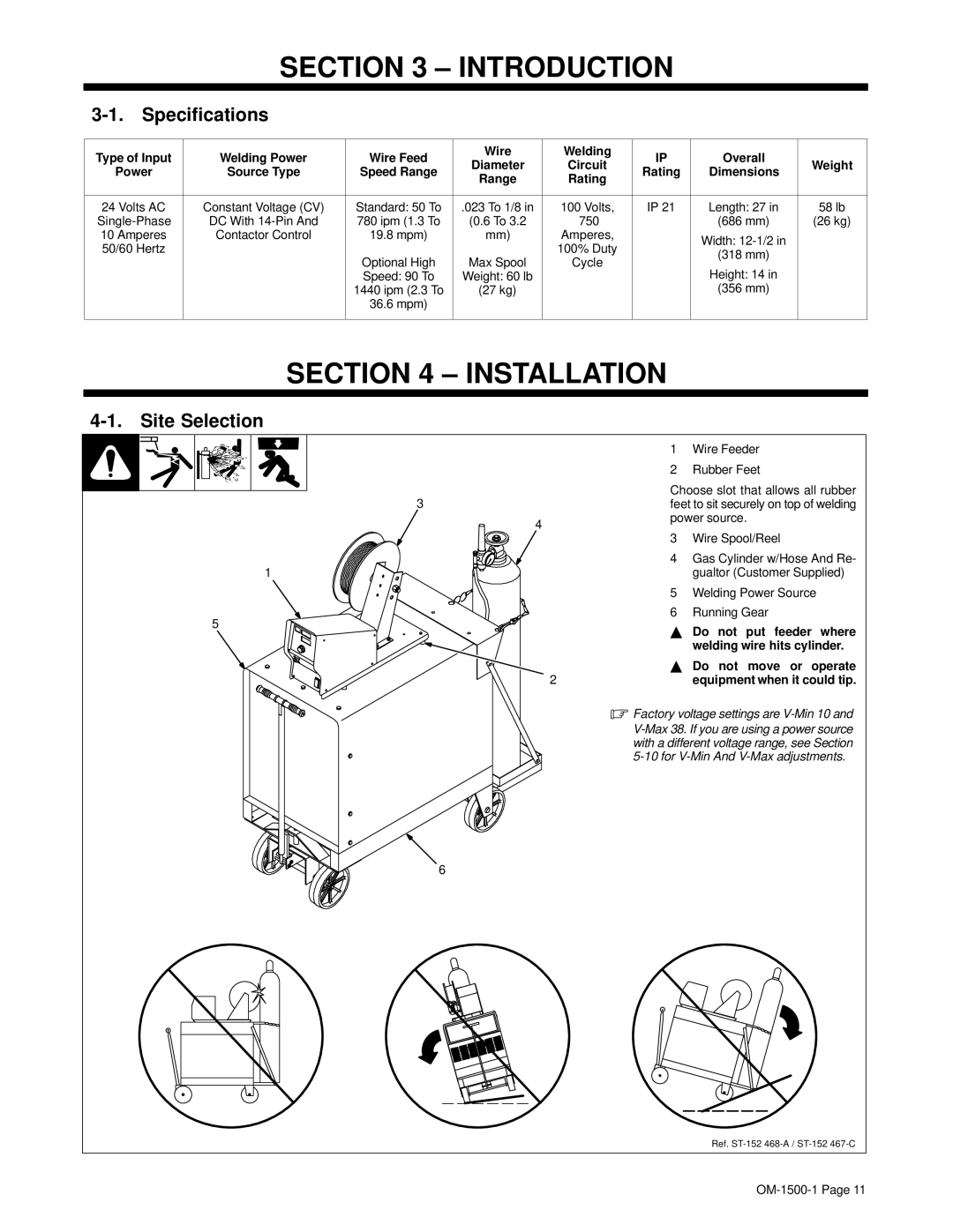
4-1. Site Selection
3
4
1
5
2
1Wire Feeder
2Rubber Feet
Choose slot that allows all rubber feet to sit securely on top of welding power source.
3Wire Spool/Reel
4Gas Cylinder w/Hose And Re- gualtor (Customer Supplied)
5Welding Power Source
6Running Gear
YDo not put feeder where welding wire hits cylinder.
YDo not move or operate equipment when it could tip.
.Factory voltage settings are
6
Ref.