5-7. Connecting To Weld Output Terminals
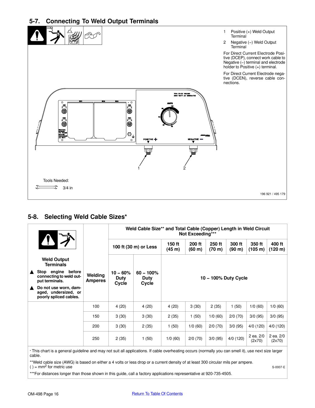
1 Positive (+) Weld Output
Terminal
2 Negative (−) Weld Output
Terminal
For Direct Current Electrode Posi- tive (DCEP), connect work cable to Negative (−) terminal and electrode holder to Positive (+) terminal.
For Direct Current Electrode nega- tive (DCEN), reverse cable con- nections.
12
Tools Needed:
3/4 in
196 921 / 495 179
5-8. Selecting Weld Cable Sizes*
|
|
|
|
| Weld Cable Size** and Total Cable (Copper) Length in Weld Circuit | |||||||
|
|
|
|
|
|
| Not Exceeding*** |
|
|
| ||
|
|
|
|
|
|
|
|
|
|
|
|
|
|
|
|
|
| 100 ft (30 m) or Less | 150 ft | 200 ft | 250 ft | 300 ft | 350 ft | 400 ft | |
|
|
|
|
| (45 m) | (60 m) | (70 m) | (90 m) | (105 m) | (120 m) | ||
| Weld Output |
|
|
| ||||||||
|
|
|
|
|
|
|
|
|
| |||
|
|
|
|
|
|
|
|
|
| |||
| Terminals |
|
|
|
|
|
|
|
|
| ||
Y Stop engine before | Welding | 10 − 60% | 60 − 100% |
|
|
|
|
|
| |||
connecting to weld out- | Duty | Duty |
| 10 − 100% Duty Cycle |
|
| ||||||
put terminals. | Amperes |
|
|
| ||||||||
Cycle | Cycle |
|
|
|
|
|
| |||||
|
|
|
|
|
|
|
|
|
|
| ||
YDo not use worn, dam- aged, undersized, or poorly spliced cables.
100 | 4 (20) | 4 (20) | 4 (20) | 3 (30) | 2 (35) | 1 (50) | 1/0 (60) | 1/0 (60) | ||
|
|
|
|
|
|
|
|
|
| |
150 | 3 (30) | 3 (30) | 2 (35) | 1 (50) | 1/0 (60) | 2/0 (70) | 3/0 (95) | 3/0 (95) | ||
|
|
|
|
|
|
|
|
|
| |
200 | 3 (30) | 2 (35) | 1 (50) | 1/0 (60) | 2/0 (70) | 3/0 (95) | 4/0 (120) | 4/0 (120) | ||
|
|
|
|
|
|
|
|
|
| |
250 | 2 (35) | 1 (50) | 1/0 (60) | 2/0 (70) | 3/0 (95) | 4/0 (120) | 2 ea. 2/0 | 2 ea. 2/0 | ||
(2x70) | (2x70) | |||||||||
|
|
|
|
|
|
|
| |||
|
|
|
|
|
|
|
|
|
| |
*This chart is a general guideline and may not suit all applications. If cable overheating occurs (normally you can smell it), use next size larger cable.
**Weld cable size (AWG) is based on either a 4 volts or less drop or a current density of at least 300 circular mils per ampere. ( ) = mm2 for metric use
***For distances longer than those shown in this guide, call a factory applications representative at
Return To Table Of Contents |