Manuals
/
Miller Electric
/
Power Tools
/
Welding System
Miller Electric
Blue Star 3500
manual
Models:
Blue Star 3500
1
57
60
60
Download
60 pages
11.47 Kb
53
54
55
56
57
58
59
60
Troubleshooting
Specification
Poor Weld Bead Characteristics
Install
Parts list
Electrical Diagrams
Symbol Usage
Plug Wired For 120/240
Dimension
Maintenance
Page 57
Image 57
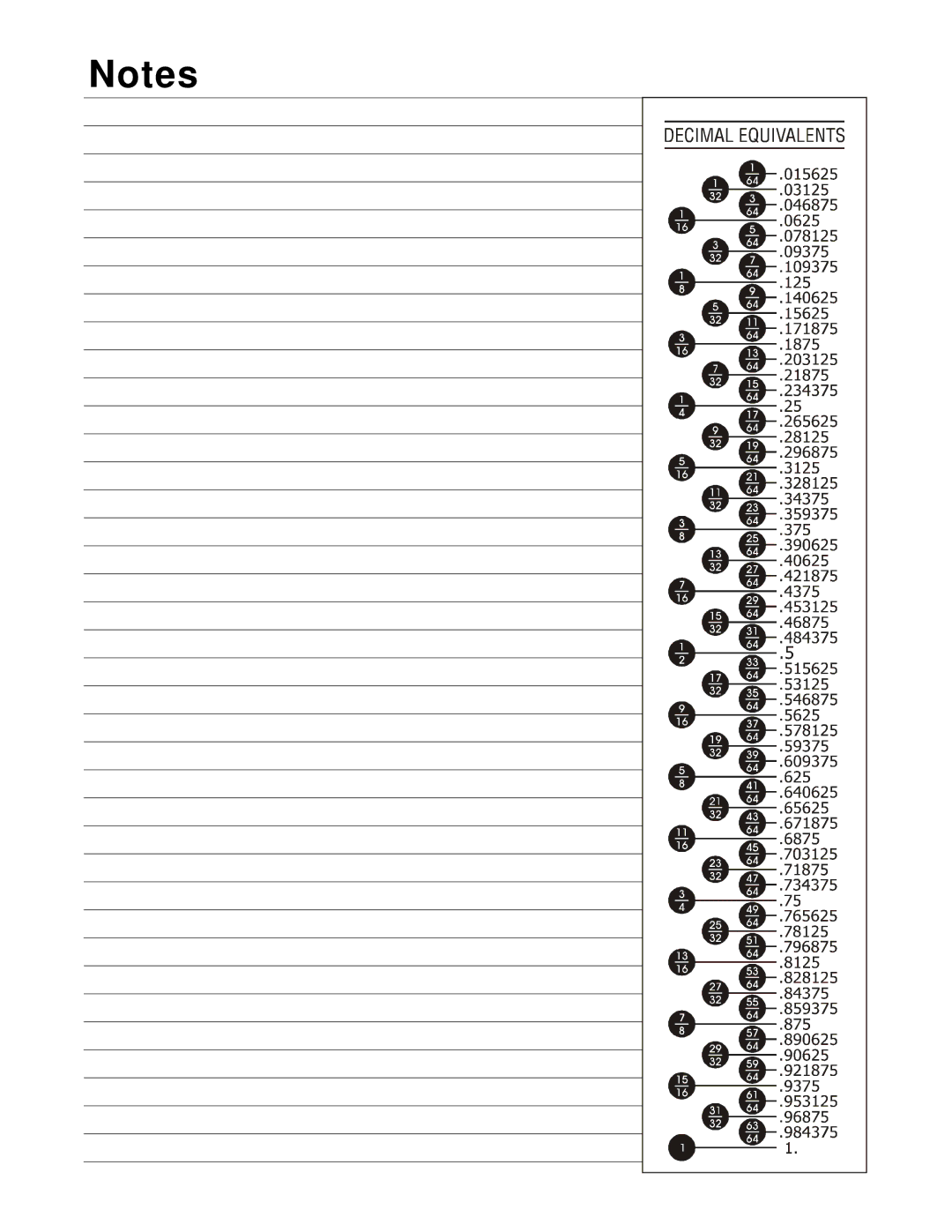
Notes
Page 56
Page 58
Page 57
Image 57
Page 56
Page 58
Contents
OM-498
Processes
Description
From Miller to You
Table of Contents
Page
Arc Welding Hazards
Symbol Usage
Engine Hazards
Compressed Air Hazards
California Proposition 65 Warnings
Principal Safety Standards
EMF Information
Radiation can cause interference
− Consignes DE Sécurité − Lire Avant Utilisation
Signification des symboles
UN Choc Électrique peut tuer
LES Fumées ET LES GAZ peuvent être dangereux
DES Particules Volantes peuvent blesser les yeux
LE Soudage peut provoquer un in- cendie ou une explosion
DES Pièces Chaudes peuvent provoquer des brûlures graves
LE Bruit peut affecter l’ouïe
DES Organes Mobiles peuvent provoquer des blessures
’EXPLOSION DE LA Batterie peut
LA Chaleur DU Moteur peut pro- voquer un incendie
’AIR Comprimé peut provoque r des blessures
Information sur les champs électromagnétiques
Principales normes de sécurité
Symbol Definitions
− Specifications
Weld, Power, And Engine Specifications
− Definitions
Fuel Consumption Kohler-Powered Units
Dimensions, Weights, And Operating Angles
Dimensions
Weight Kohler-Powered Units
Exceeding duty cycle can damage unit and void warranty
Fuel Consumption Honda-Powered Units
Duty Cycle
100% Duty Cycle at 80 Amperes CC/DC
Volt-Ampere Curves
Generator Power Curve
− Installation
Installing Welding Generator
Grounding Generator To Truck Or Trailer Frame
Use ground device as stated in electrical codes
Grounding Generator When Supplying Building Systems
Connecting The Battery Honda Electric-Start Models Only
Engine Prestart Checks Honda-Powered Units
+ −
Oil
Selecting Weld Cable Sizes
Connecting To Weld Output Terminals
− Operating the Welding Generator
Controls Kohler-Powered Units
60 Hz
Choke Control Lever
Recoil-Start 2Electric-Start
Controls Honda-Powered Units See Section
Work like a Pro
Description Of Controls Honda-Powered Units See Section
Generator Power Panel 495 218 USA
− Operating Auxiliary Equipment
120 V x 10 a + 240 V x 9 a = 3.5 kVA/ KW OM-498
Generator Power Panel 495
Optional Generator Power Panels
Canada South Africa South America
Australia Europe Asia
It exceeds 3500W
Generator Power Panel Ratings
Wire Load
Plug Wired For 120/240
Plex receptacle shares a load with
One half of the 240 V receptacle
− Maintenance
Overload Protection Honda-Powered Units Only
Maintenance Label
Weld/Power Speed Adjustment
Adjusting Engine Speed Kohler-Powered Units
Top View Idle Speed Adjustment
Stop engine. Close fuel valve Top View
Throttle Control Lever Adjustment Screw
Adjusting Engine Speed Honda-Powered Units
Stop engine. Close fuel valve
Tools Needed 3/8
Troubleshooting
− Troubleshooting
Generator Power
Welding
Viscosity oil for operating temperature
Check battery voltage Honda electric-start models only
Engine
Make starting difficult
Circuit Diagram For Welding Generator
− Electrical Diagrams
Wiring Diagram For Generator Power Panels 1
Wiring Diagram For Generator Power Panels 2
− Generator Power Guidelines
Selecting Equipment
OM-491
How Much Power Does Equipment Require?
Grounding When Supplying Building Systems
Earth ground if supplying
Volts 115 Amps Resistive Load
Approximate Power Requirements For Farm/Home Equipment
Approximate Power Requirements For Industrial Motors
Industrial Motors Rating Starting Watts Running Watts
Farm/Home Equipment Rating Starting Watts Running Watts
Contractor Rating Starting Watts Running Watts
Approximate Power Requirements For Contractor Equipment
How Much Power Can Generator Supply?
Power Required To Start Motor
Single-Phase Induction Motor Starting Requirements
KVA/HP x HP x
Typical Connections To Supply Standby Power
Current Load Watts Amperes
Selecting Extension Cord Use Shortest Cord Possible
Stick Welding Procedure
Weld current starts when electrode touches work- piece
− Stick Welding Smaw Guidelines
Electrode and Amperage Selection Chart
Striking an Arc − Scratch Start Technique
Striking an Arc − Tapping Technique
Good Weld Bead Characteristics
Poor Weld Bead Characteristics
Positioning Electrode Holder
10-30 9090 End View of Work Angle
Electrode Movement During Welding
Conditions That Affect Weld Bead Shape
Lap Joint
Butt Joints
Tee Joint
16 in 1.6 mm Tack Welds
Troubleshooting − Excessive Spatter
Troubleshooting − Porosity
Weld Test
Possible Causes Corrective Actions
Troubleshooting − Incomplete Fusion
Troubleshooting − Lack Of Penetration
Troubleshooting − Excessive Penetration
Troubleshooting − Burn-Through
Troubleshooting − Waviness Of Bead
Troubleshooting − Distortion
31−Fig
− Parts List
Dia Part
Generator Power Panel 495 South Africa Australia
Generator Power Panel 495 Generator Power Panel 495 315 USA
Canada
Europe America
Generator Power Panel 495 279 Canada
Generator Power Panel 495 218 USA
Generator Power Panel 495 253 South Africa
Generator Power Panel 495 289 Australia
Work like a Pro
Page
TM-188 304 Invision 354MP
Material Thickness Reference Chart
Service
Your distributor also gives
Support
For assistance in filing or settling claims, contact
Miller Electric Mfg. Co
Your distributor and/or equipment manufacturer’s
Transportation Department
Top
Page
Image
Contents