If supplied remote control cord is not suitable for con- necting to the REMOTE 9 receptacle RC3, proceed with one of the following alternatives;

1. Wire a plug or cord to interface with REMOTE 9

F

GE

I

HD

receptacle RC3 using socket information in Sec-

A

C

tion C.

2. Wire remote control cord directly to terminal strip

within unit according to Section B.

B. REMOTE Terminal Strip 3T Information And

Connections (Figures 4-2 And 4-4)

WARNING: ELECTRIC SHOCK can kill; UN- EXPECTED OUTPUT can cause serious in- jury.

Do not touch live electrical parts.

Stop engine, and disconnect negative (−) battery cable from battery before making any internal inspection or connections.

Do not connect to REMOTE 9 receptacle and terminal strip at the same time.

Since the OUTPUT (CONTACTOR) can be en- ergized from either the receptacle or terminal strip, it is vital to use only one remote control method.

MOVING PARTS can cause serious injury.

Keep away from moving parts such as fans, belts, and rotors.

Terminal strip 3T, mounted on the lower front panel (see Figure 4-2), is included in case the plug supplied on the remote control cord is not suitable for connections to the REMOTE 9 receptacle RC3.

To make connections, proceed as follows:

1.Remove existing plug from remote control cord.

2.Open and secure lower front door.

3.Locate strain reliefs provided on lower front panel (see Figure 4-2).

4.Insert leads from cord through strain relief.

5.For Remote Electrical Cutoff Switch, remove jumper link between terminals N and P.

6.Connect leads to terminal strip 3T using terminal information provided in Section C.

7.Secure the cord in the strain relief.

8.Close and secure door.

C. Socket/Terminal Information (Figure 4-4)

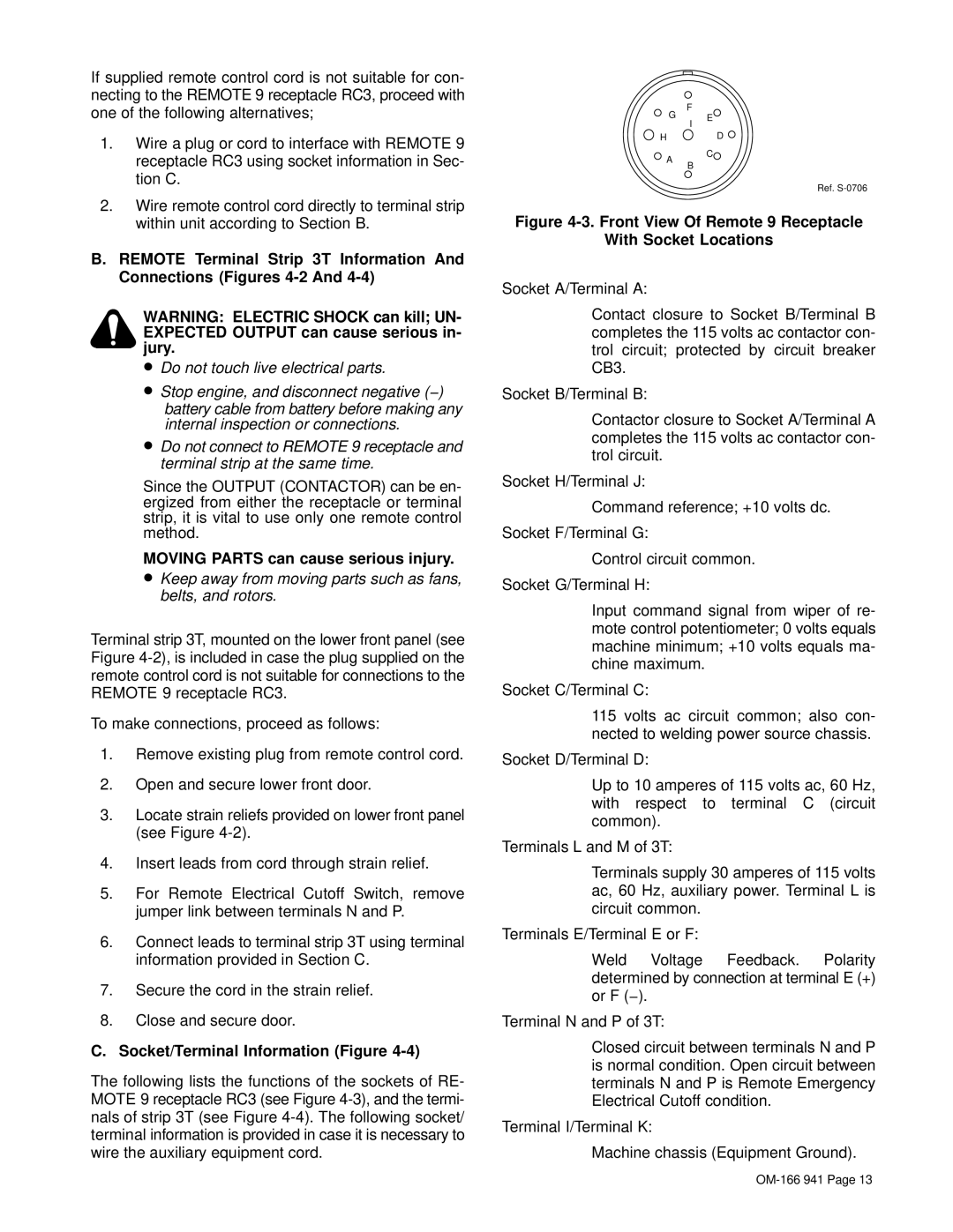
The following lists the functions of the sockets of RE- MOTE 9 receptacle RC3 (see Figure 4-3), and the termi- nals of strip 3T (see Figure 4-4). The following socket/ terminal information is provided in case it is necessary to wire the auxiliary equipment cord.

B

Ref. S-0706

Figure 4-3. Front View Of Remote 9 Receptacle

With Socket Locations

Socket A/Terminal A:

Contact closure to Socket B/Terminal B completes the 115 volts ac contactor con- trol circuit; protected by circuit breaker CB3.

Socket B/Terminal B:

Contactor closure to Socket A/Terminal A completes the 115 volts ac contactor con- trol circuit.

Socket H/Terminal J:

Command reference; +10 volts dc.

Socket F/Terminal G:

Control circuit common.

Socket G/Terminal H:

Input command signal from wiper of re- mote control potentiometer; 0 volts equals machine minimum; +10 volts equals ma- chine maximum.

Socket C/Terminal C:

115 volts ac circuit common; also con- nected to welding power source chassis.

Socket D/Terminal D:

Up to 10 amperes of 115 volts ac, 60 Hz, with respect to terminal C (circuit common).

Terminals L and M of 3T:

Terminals supply 30 amperes of 115 volts ac, 60 Hz, auxiliary power. Terminal L is circuit common.

Terminals E/Terminal E or F:

Weld Voltage Feedback. Polarity determined by connection at terminal E (+) or F (−).

Terminal N and P of 3T:

Closed circuit between terminals N and P is normal condition. Open circuit between terminals N and P is Remote Emergency Electrical Cutoff condition.

Terminal I/Terminal K:

Machine chassis (Equipment Ground).

OM-166 941 Page 13

Page 18
Image 18
Miller Electric CBI 801D Tion C, Wire remote control cord directly to terminal strip, Within unit according to Section B

CBI 801D specifications

The Miller Electric CBI 801D is a robust and sophisticated multi-process welder, designed for maximum efficiency and versatility in various welding applications. This machine stands out due to its combination of advanced technology and user-friendly design, making it suitable for both seasoned professionals and those new to welding.

One of the key features of the CBI 801D is its ability to perform multiple welding processes, including MIG, TIG, and stick welding. This multi-functionality allows users to tackle a wide range of welding tasks, whether they are working on thin sheet metals or heavy fabrication. The seamless transition between processes is designed to enhance productivity and reduce downtime.

The CBI 801D is powered by Miller's innovative Auto-Set technology, which automatically adjusts the machine settings based on the material type and thickness. This feature simplifies the setup process, allowing welders to focus more on their work rather than on configuring the machine. Additionally, the user interface is designed for simplicity, featuring intuitive controls that are easy to navigate.

In terms of performance, the CBI 801D delivers impressive output, with a maximum welding output of 800 amps. This substantial power provides the capability to weld thicker materials with greater efficiency, making it an ideal choice for industrial applications. The built-in advanced cooling system ensures optimal performance during extended use, preventing overheating and maintaining consistent weld quality.

Durability is another hallmark of the Miller Electric CBI 801D. The machine is constructed with high-quality materials, providing resilience against tough working conditions. Its compact and portable design allows for easy transport to various job sites, while the built-in handles are designed for convenience.

Moreover, the CBI 801D features advanced digital readouts for real-time monitoring of welding parameters. This not only enhances precision but also allows welders to make necessary adjustments on the fly. The machine is also compatible with various accessories, which further expand its functionality and adaptability across different welding scenarios.

In summary, the Miller Electric CBI 801D is a powerful and versatile welding machine, offering multi-process capabilities, user-friendly features, and a robust design. Its combination of advanced technology and reliable performance makes it a top choice for professionals looking for efficiency and precision in their welding tasks. Whether for fabrication, repair, or maintenance, the CBI 801D proves to be an invaluable asset in any welding operation.