Welding

Generator

Load Bank

Positive (+)


Negative (−)


Weld Output

+

Weld Output

+

Voltmeter

Terminal


Terminal


And


Ammeter


Weld


Cables

S-0456

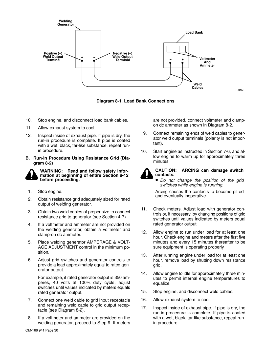
Diagram 8-1. Load Bank Connections

10.Stop engine, and disconnect load bank cables.

11.Allow exhaust system to cool.

12.Inspect inside of exhaust pipe. If pipe is dry, the run-in procedure is complete. If pipe is coated with a wet, black, tar-like substance, repeat run- in procedure.

B.Run-In Procedure Using Resistance Grid (Dia- gram 8-2)

WARNING: Read and follow safety infor- mation at beginning of entire Section 8-12 before proceeding.

1.Stop engine.

2.Obtain resistance grid adequately sized for rated output of welding generator.

3.Obtain two weld cables of proper size to connect resistance grid to generator (see Section 4-7).

4.If a voltmeter and ammeter are not provided on the welding generator, obtain a voltmeter and clamp-on dc ammeter.

5.Place welding generator AMPERAGE & VOLT- AGE ADJUSTMENT control in the minimum po- sition.

6.Adjust grid switches and generator controls to provide a load approximately equal to rated gen- erator output.

For example, if rated generator output is 350 am- peres, 40 volts at 100% duty cycle, adjust switches until values indicated by meters equals rated generator output.

7.Connect one weld cable to grid input receptacle and remaining weld cable to grid output recep- tacle (see Diagram 8-2).

8.If a voltmeter and ammeter are provided on the welding generator, proceed to Step 9. If meters

are not provided, connect voltmeter and clamp- on dc ammeter as shown in Diagram 8-2.

9.Connect remaining ends of weld cables to gener- ator weld output terminals (polarity is not impor- tant).

10.Start engine as instructed in Section 7-6, and al- low engine to warm up for approximately three minutes.

CAUTION: ARCING can damage switch contacts.

Do not change the position of the grid switches while engine is running.

Arcing causes the contacts to become pitted and eventually inoperative.

11.Check meters. Adjust load with generator con- trols or, if necessary, by changing positions of grid switches until values indicated by meters equal rated generator output.

12.Allow engine to run under load for at least one hour. Check engine and meters after the first five minutes and every 15 minutes thereafter to be sure equipment is operating properly

13.After running engine under load for at least one hour, remove load by shutting down resistance grid.

14.Allow engine to idle for approximately three min- utes to permit internal engine temperatures to equalize.

15.Stop engine, and disconnect weld cables.

16.Allow exhaust system to cool.

17.Inspect inside of exhaust pipe. If pipe is dry, the run-in procedure is complete. If pipe is coated with a wet, black, tar-like substance, repeat run- in procedure.

OM-166 941 Page 30

Page 35
Image 35
Miller Electric CBI 801D manual Diagram 8-1. Load Bank Connections, Run-In Procedure Using Resistance Grid Dia- gram

CBI 801D specifications

The Miller Electric CBI 801D is a robust and sophisticated multi-process welder, designed for maximum efficiency and versatility in various welding applications. This machine stands out due to its combination of advanced technology and user-friendly design, making it suitable for both seasoned professionals and those new to welding.

One of the key features of the CBI 801D is its ability to perform multiple welding processes, including MIG, TIG, and stick welding. This multi-functionality allows users to tackle a wide range of welding tasks, whether they are working on thin sheet metals or heavy fabrication. The seamless transition between processes is designed to enhance productivity and reduce downtime.

The CBI 801D is powered by Miller's innovative Auto-Set technology, which automatically adjusts the machine settings based on the material type and thickness. This feature simplifies the setup process, allowing welders to focus more on their work rather than on configuring the machine. Additionally, the user interface is designed for simplicity, featuring intuitive controls that are easy to navigate.

In terms of performance, the CBI 801D delivers impressive output, with a maximum welding output of 800 amps. This substantial power provides the capability to weld thicker materials with greater efficiency, making it an ideal choice for industrial applications. The built-in advanced cooling system ensures optimal performance during extended use, preventing overheating and maintaining consistent weld quality.

Durability is another hallmark of the Miller Electric CBI 801D. The machine is constructed with high-quality materials, providing resilience against tough working conditions. Its compact and portable design allows for easy transport to various job sites, while the built-in handles are designed for convenience.

Moreover, the CBI 801D features advanced digital readouts for real-time monitoring of welding parameters. This not only enhances precision but also allows welders to make necessary adjustments on the fly. The machine is also compatible with various accessories, which further expand its functionality and adaptability across different welding scenarios.

In summary, the Miller Electric CBI 801D is a powerful and versatile welding machine, offering multi-process capabilities, user-friendly features, and a robust design. Its combination of advanced technology and reliable performance makes it a top choice for professionals looking for efficiency and precision in their welding tasks. Whether for fabrication, repair, or maintenance, the CBI 801D proves to be an invaluable asset in any welding operation.