WARNING: ELECTRIC SHOCK can kill.
Do not touch live electrical parts.
Stop engine, and disconnect negative (−) battery cable from battery before beginning this installation.
MOVING PARTS can cause serious injury.
Keep away from moving parts such as fans, belts, and rotors.
HOT SURFACES can cause severe burns.
Wear protective gloves and clothing when working near a hot engine.
Allow components to cool completely be- fore touching.
IMPORTANT: All directions, such as left or right, are with respect to the operator facing the welding generator front panel. Retain all hardware removed during this procedure for reinstallation unless specifically told otherwise.
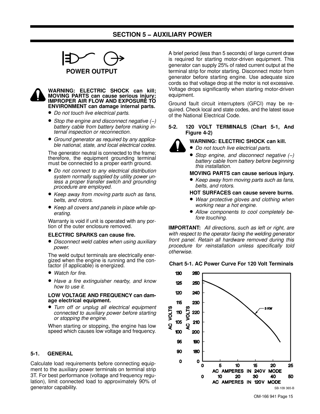
Chart 5-1. AC Power Curve For 120 Volt Terminals
SB-109365-BOM-166 941 Page 15
TERMINALS (Chart 5-1, And

SECTION 5 − AUXILIARY POWER

POWER OUTPUT

WARNING: ELECTRIC SHOCK can kill; MOVING PARTS can cause serious injury;

IMPROPER AIR FLOW AND EXPOSURE TO ENVIRONMENT can damage internal parts.

Do not touch live electrical parts.

Stop the engine and disconnect negative (−) battery cable from battery before making in- ternal inspection or reconnection.

Ground generator as required by any applica- ble national, state, and local electrical codes.

The generator neutral is connected to the frame; therefore, the equipment grounding terminal must be connected to a proper earth ground.

Do not connect to any electrical distribution system normally supplied by utility power un- less a proper transfer switch and grounding procedure are employed.

Keep away from moving parts such as fans, belts, and rotors.

Keep all covers and panels in place while op- erating.

Warranty is void if unit is operated with any por- tion of the outer enclosure removed.

ELECTRIC SPARKS can cause fire.

Disconnect weld cables when using auxiliary power.

The weld output terminals are electrically ener- gized when the engine is running and the con- tactor (if applicable) is energized.

Watch for fire.

Have a fire extinguisher nearby, and know how to use it.

LOW VOLTAGE AND FREQUENCY can dam- age electrical equipment.

Turn off or unplug all electrical equipment connected to auxiliary power before starting or stopping the engine.

When starting or stopping, the engine has low speed which causes low voltage and frequency.

5-1. GENERAL

Calculate load requirements before connecting equip- ment to the auxiliary power terminals on terminal strip 3T. For best performance (voltage and frequency regu- lation), limit connected load to approximately 90% of generator capability.

A brief period (less than 5 seconds) of large current draw is required for starting motor-driven equipment. This generator can supply 25% of rated current output at the terminal strip for motor starting. Disconnect motor from generator before starting engine. Use adequate size cords so that voltage drop at the motor is not excessive. Voltage drops significantly when starting motor-driven equipment.

Ground fault circuit interrupters (GFCI) may be re- quired. Check local and state codes, and the latest issue of the National Electrical Code.

5-2. 120 VOLT Figure 4-2)

Page 20
Image 20
Miller Electric CBI 801D manual Auxiliary Power Power Output, Electric Sparks can cause fire, General, Volt Figure

CBI 801D specifications

The Miller Electric CBI 801D is a robust and sophisticated multi-process welder, designed for maximum efficiency and versatility in various welding applications. This machine stands out due to its combination of advanced technology and user-friendly design, making it suitable for both seasoned professionals and those new to welding.

One of the key features of the CBI 801D is its ability to perform multiple welding processes, including MIG, TIG, and stick welding. This multi-functionality allows users to tackle a wide range of welding tasks, whether they are working on thin sheet metals or heavy fabrication. The seamless transition between processes is designed to enhance productivity and reduce downtime.

The CBI 801D is powered by Miller's innovative Auto-Set technology, which automatically adjusts the machine settings based on the material type and thickness. This feature simplifies the setup process, allowing welders to focus more on their work rather than on configuring the machine. Additionally, the user interface is designed for simplicity, featuring intuitive controls that are easy to navigate.

In terms of performance, the CBI 801D delivers impressive output, with a maximum welding output of 800 amps. This substantial power provides the capability to weld thicker materials with greater efficiency, making it an ideal choice for industrial applications. The built-in advanced cooling system ensures optimal performance during extended use, preventing overheating and maintaining consistent weld quality.

Durability is another hallmark of the Miller Electric CBI 801D. The machine is constructed with high-quality materials, providing resilience against tough working conditions. Its compact and portable design allows for easy transport to various job sites, while the built-in handles are designed for convenience.

Moreover, the CBI 801D features advanced digital readouts for real-time monitoring of welding parameters. This not only enhances precision but also allows welders to make necessary adjustments on the fly. The machine is also compatible with various accessories, which further expand its functionality and adaptability across different welding scenarios.

In summary, the Miller Electric CBI 801D is a powerful and versatile welding machine, offering multi-process capabilities, user-friendly features, and a robust design. Its combination of advanced technology and reliable performance makes it a top choice for professionals looking for efficiency and precision in their welding tasks. Whether for fabrication, repair, or maintenance, the CBI 801D proves to be an invaluable asset in any welding operation.