5-3. Rear Panel Connections And Rotating Drive Assembly
1
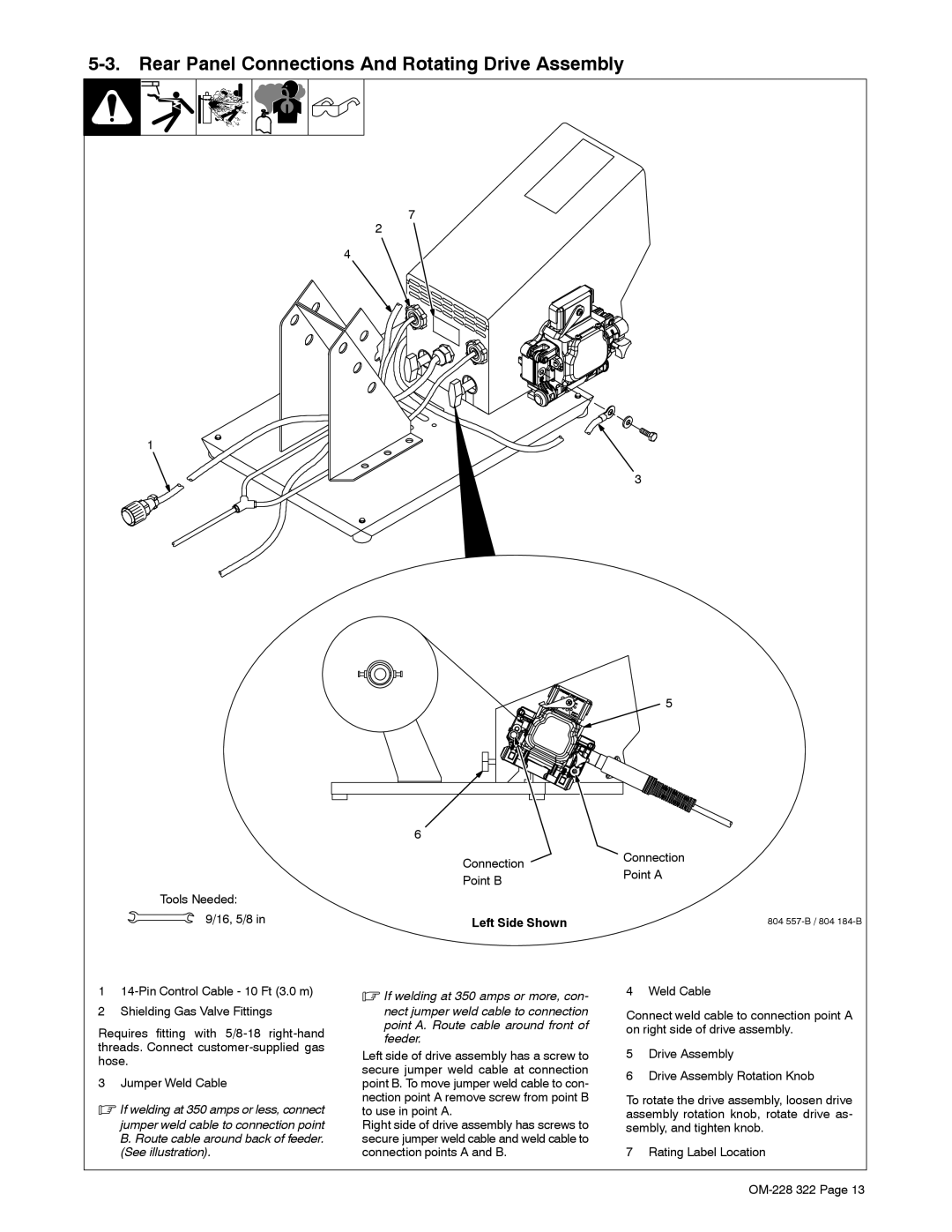
Tools Needed: 9/16, 5/8 in
7
2
4
3
5
6
Connection | Connection | |
Point A | ||
Point B | ||
| ||
Left Side Shown | 804 |
1
2Shielding Gas Valve Fittings
Requires fitting with
3 Jumper Weld Cable
.If welding at 350 amps or less, connect
jumper weld cable to connection point B. Route cable around back of feeder. (See illustration).
.If welding at 350 amps or more, con-
nect jumper weld cable to connection point A. Route cable around front of feeder.
Left side of drive assembly has a screw to secure jumper weld cable at connection point B. To move jumper weld cable to con- nection point A remove screw from point B to use in point A.
Right side of drive assembly has screws to secure jumper weld cable and weld cable to connection points A and B.
4 Weld Cable
Connect weld cable to connection point A on right side of drive assembly.
5Drive Assembly
6Drive Assembly Rotation Knob
To rotate the drive assembly, loosen drive assembly rotation knob, rotate drive as- sembly, and tighten knob.
7 Rating Label Location