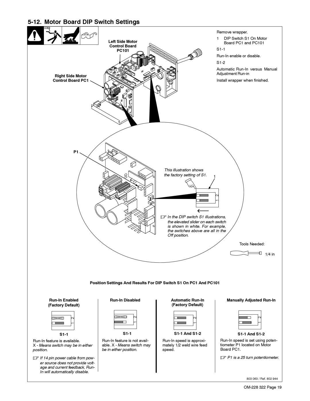
5-12. Motor Board DIP Switch Settings
Left Side Motor
Control Board
PC101
Right Side Motor
Control Board PC1
P1
Remove wrapper.
1DIP Switch S1 On Motor Board PC1 and PC101
Automatic
Adjustment
Install wrapper when finished.
This illustration shows |
|
the factory setting of S1. | 1 |
|
.In the DIP switch S1 illustrations,
the elevated slider on each switch is shown in white. For example, the switches above are all in the Off position.
Tools Needed:
1/4 in
Position Settings And Results For DIP Switch S1 On PC1 And PC101
(Factory Default)
X - Means switch may be in either position.
.If 14 pin power cable from pow-
er source does not provide volt- age and current feedback, Run- In will automatically disable.
Run-In Disabled
S1-1
Automatic
S1-1 And S1-2
Manually Adjusted Run-In
S1-1 And S1-2
.P1 is a 25 turn potentiometer.
803 063 / Ref. 802 944