5:8
Camera body 503CW
Fitting the Circuit board (22575) *22882
CAUTION! When handling the circuit board a grounded bench mat and a wrist strap must be used to prevent ESD damage.
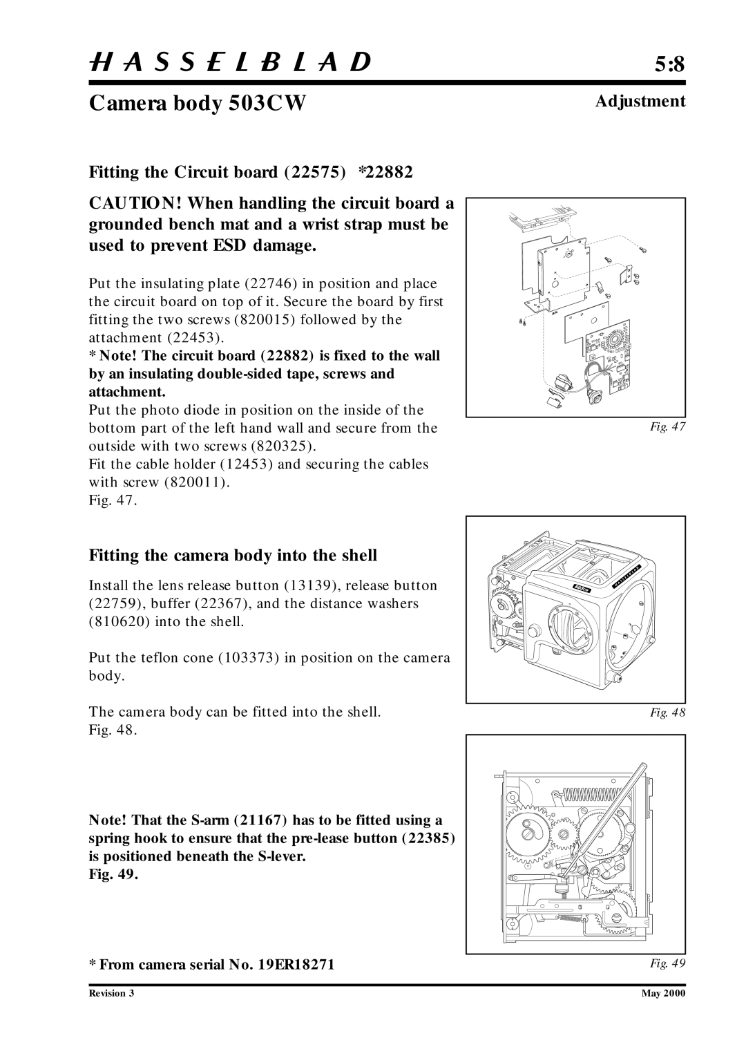
Put the insulating plate (22746) in position and place the circuit board on top of it. Secure the board by first fitting the two screws (820015) followed by the attachment (22453).
*Note! The circuit board (22882) is fixed to the wall by an insulating
Put the photo diode in position on the inside of the bottom part of the left hand wall and secure from the outside with two screws (820325).
Fit the cable holder (12453) and securing the cables with screw (820011).
Fig. 47.
Adjustment
Fig. 47
Fitting the camera body into the shell
Install the lens release button (13139), release button (22759), buffer (22367), and the distance washers (810620) into the shell.
Put the teflon cone (103373) in position on the camera body.
The camera body can be fitted into the shell. Fig. 48.
Note! That the
Fig. 49.
* From camera serial No. 19ER18271
Revision 3
Fig. 48
Fig. 49
May 2000
