4:6
Camera body 503CW | Reassembly |
Front plate (30777)
Fitting the front bayonet plate to the camera body
Tension the drive spring by turning the outer gear wheel clockwise four turns. The front key will be positioned at the red index dot.
A locking pin can be inserted through the inner cog wheel and the bracket to prevent the spring from unwinding.
Install the winding knob
Note! Make sure the
Fig.25.
Fig. 25
Install the front bayonet plate. Ensure that the push rod (22369) passes through the hole in the front plate and that the lens lock pin (13280) passes through the appropriate hole when the front plate is fitted and secured.
Secure the two screws (823655) in the bottom plate and seal with loctite. Secure the four screws (820015) in the left and right hand walls, and the two screws (821017) in the focusing screen frame.
Remove the temporary locking pin.
Fig. 26.
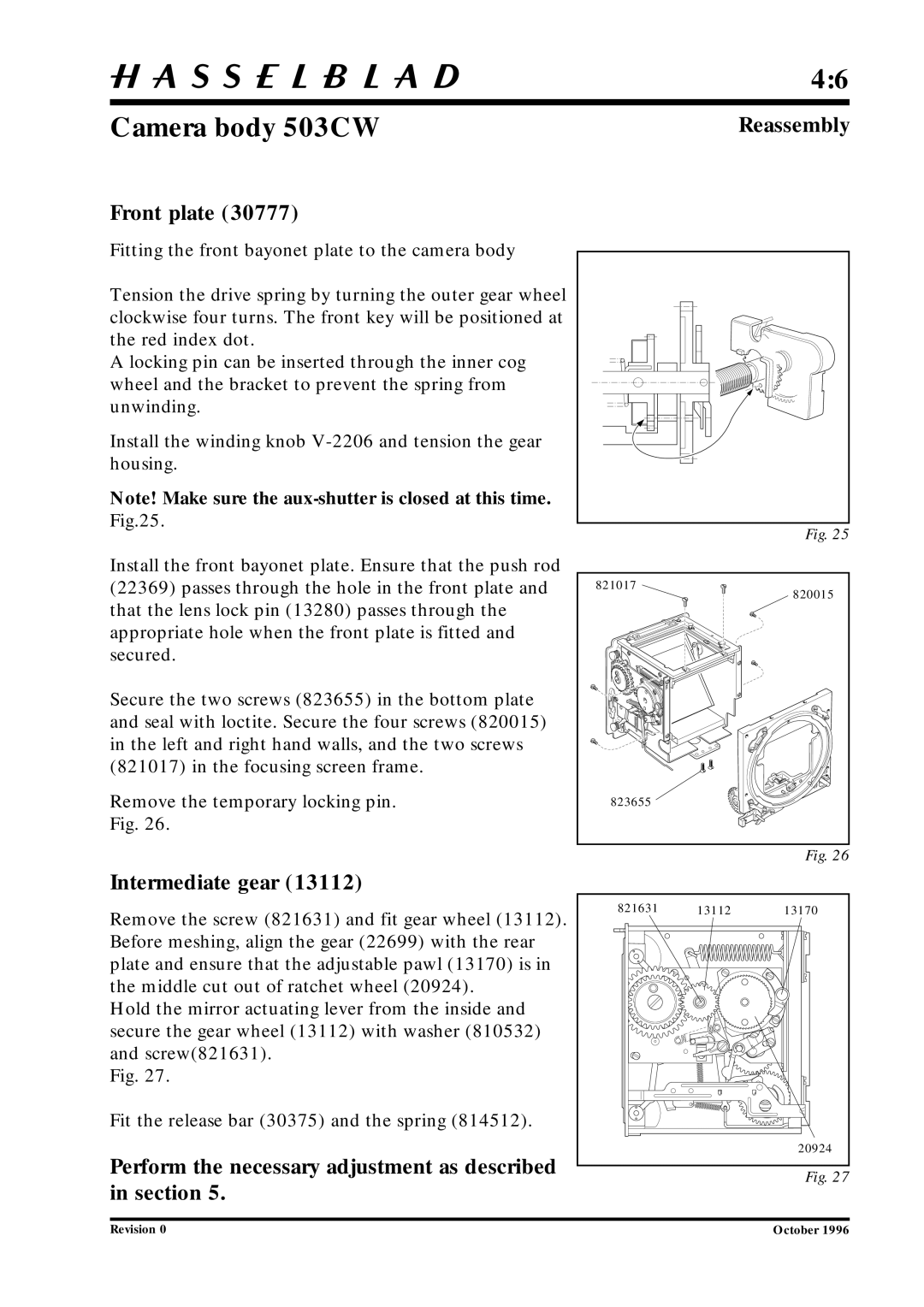
Intermediate gear (13112)
821017 |
820015 |
823655 |
Fig. 26
Remove the screw (821631) and fit gear wheel (13112). Before meshing, align the gear (22699) with the rear plate and ensure that the adjustable pawl (13170) is in the middle cut out of ratchet wheel (20924).
Hold the mirror actuating lever from the inside and secure the gear wheel (13112) with washer (810532) and screw(821631).
Fig. 27.
Fit the release bar (30375) and the spring (814512).
Perform the necessary adjustment as described in section 5.
821631 | 13112 | 13170 |
|
| 20924 |
Fig. 27
Revision 0 | October 1996 |