4:4
Camera body 503CW | Reassembly |
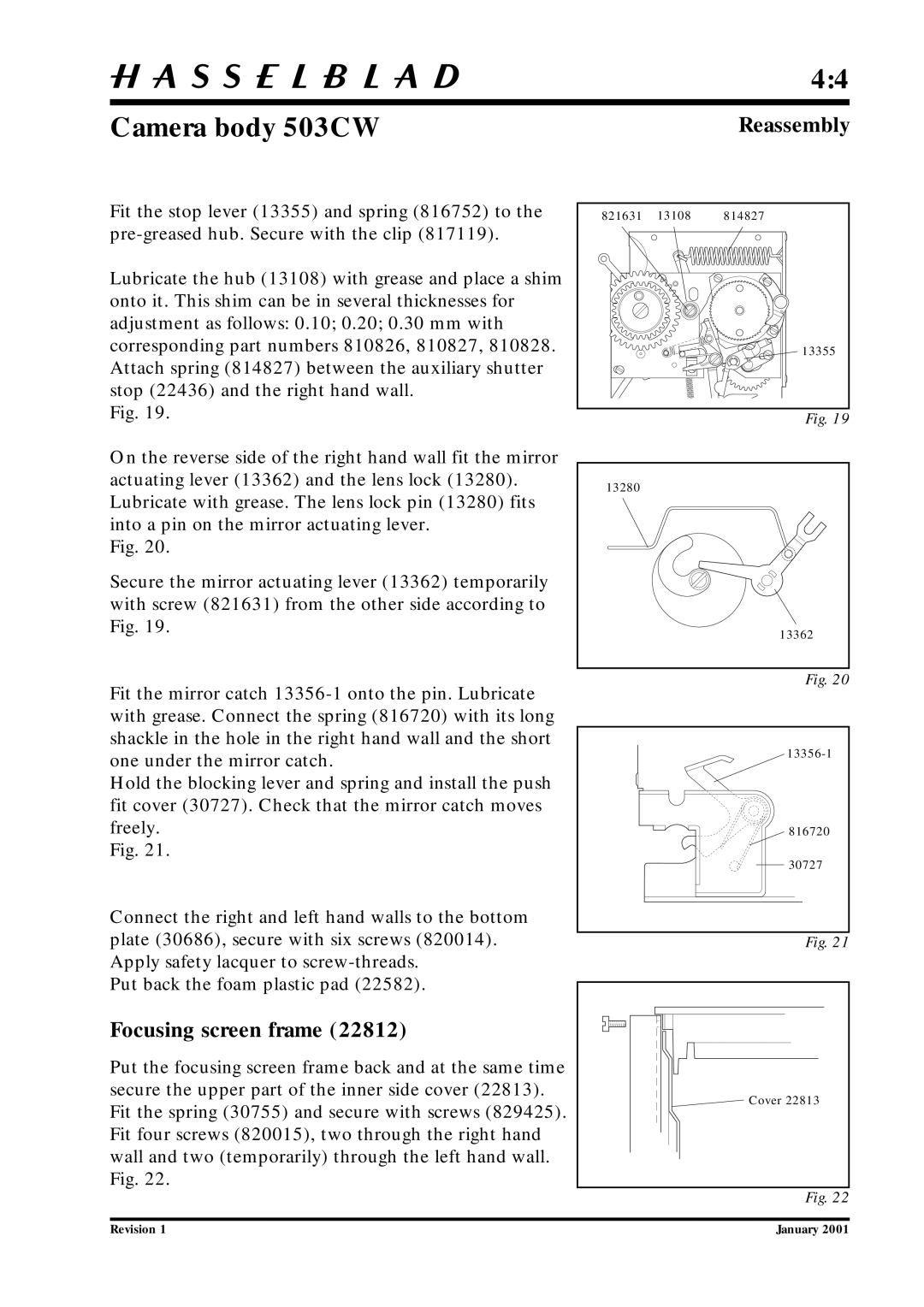
Fit the stop lever (13355) and spring (816752) to the
Lubricate the hub (13108) with grease and place a shim onto it. This shim can be in several thicknesses for adjustment as follows: 0.10; 0.20; 0.30 mm with corresponding part numbers 810826, 810827, 810828. Attach spring (814827) between the auxiliary shutter stop (22436) and the right hand wall.
Fig. 19.
On the reverse side of the right hand wall fit the mirror actuating lever (13362) and the lens lock (13280). Lubricate with grease. The lens lock pin (13280) fits into a pin on the mirror actuating lever.
Fig. 20.
Secure the mirror actuating lever (13362) temporarily with screw (821631) from the other side according to Fig. 19.
821631 | 13108 | 814827 |
13355
Fig. 19
13280
13362
Fit the mirror catch
Hold the blocking lever and spring and install the push fit cover (30727). Check that the mirror catch moves freely.
Fig. 21.
Connect the right and left hand walls to the bottom plate (30686), secure with six screws (820014). Apply safety lacquer to
Put back the foam plastic pad (22582).
Focusing screen frame (22812)
Put the focusing screen frame back and at the same time secure the upper part of the inner side cover (22813). Fit the spring (30755) and secure with screws (829425). Fit four screws (820015), two through the right hand wall and two (temporarily) through the left hand wall. Fig. 22.
Fig. 20
816720
30727
Fig. 21
Cover 22813 |
Fig. 22
Revision 1 | January 2001 |
