4:3
Camera body 503CW | Reassembly |
Fitting the mechanism plate to the right hand wall
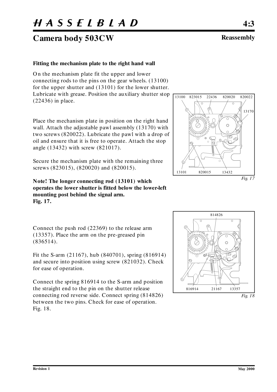
On the mechanism plate fit the upper and lower connecting rods to the pins on the gear wheels. (13100) for the upper shutter and (13101) for the lower shutter. Lubricate with grease. Position the auxiliary shutter stop (22436) in place.
Place the mechanism plate in position on the right hand wall. Attach the adjustable pawl assembly (13170) with two screws (820022). Lubricate the pawl with a drop of oil and ensure that it is free to operate. Attach the stop angle (13432) with screw (821017).
Secure the mechanism plate with the remaining three screws (823015), (820020) and (820015).
Note! The longer connecting rod (13101) which operates the lower shutter is fitted below the
Fig. 17.
13100 | 823015 | 22436 | 820020 | 820022 |
|
|
|
| 13170 |
13101 | 820015 | 13432 |
| |
Fig. 17
Connect the push rod (22369) to the release arm (13357). Place the arm on the
Fit the
Connect the spring 816914 to the
| 814826 |
|
816914 | 21167 | 13357 |
Fig. 18
Revision 1 | May 2000 |