5:10
Camera body 503CW | Adjustment |
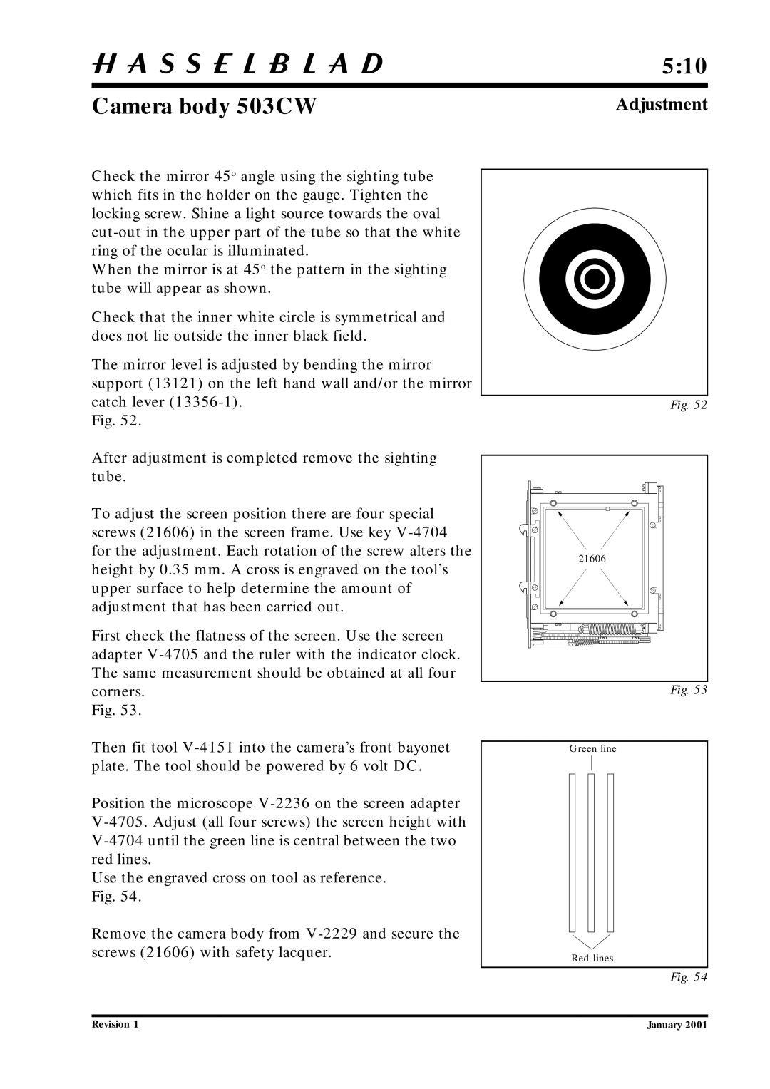
Check the mirror 45o angle using the sighting tube which fits in the holder on the gauge. Tighten the locking screw. Shine a light source towards the oval
When the mirror is at 45o the pattern in the sighting tube will appear as shown.
Check that the inner white circle is symmetrical and does not lie outside the inner black field.
The mirror level is adjusted by bending the mirror support (13121) on the left hand wall and/or the mirror catch lever
Fig. 52.
After adjustment is completed remove the sighting tube.
To adjust the screen position there are four special screws (21606) in the screen frame. Use key
First check the flatness of the screen. Use the screen adapter
Fig. 53.
Then fit tool
Position the microscope
Use the engraved cross on tool as reference. Fig. 54.
Remove the camera body from
Fig. 52
21606 |
Fig. 53
Green line
Red lines
Fig. 54
Revision 1 | January 2001 |