| 5:2 | |
Camera body 503CW | Adjustment | |
Focal length |
| |
The camera body’s focal length is inspected and |
| |
adjusted by using tool |
| |
71.40 mm ± 0.03 mm. | "B" | |
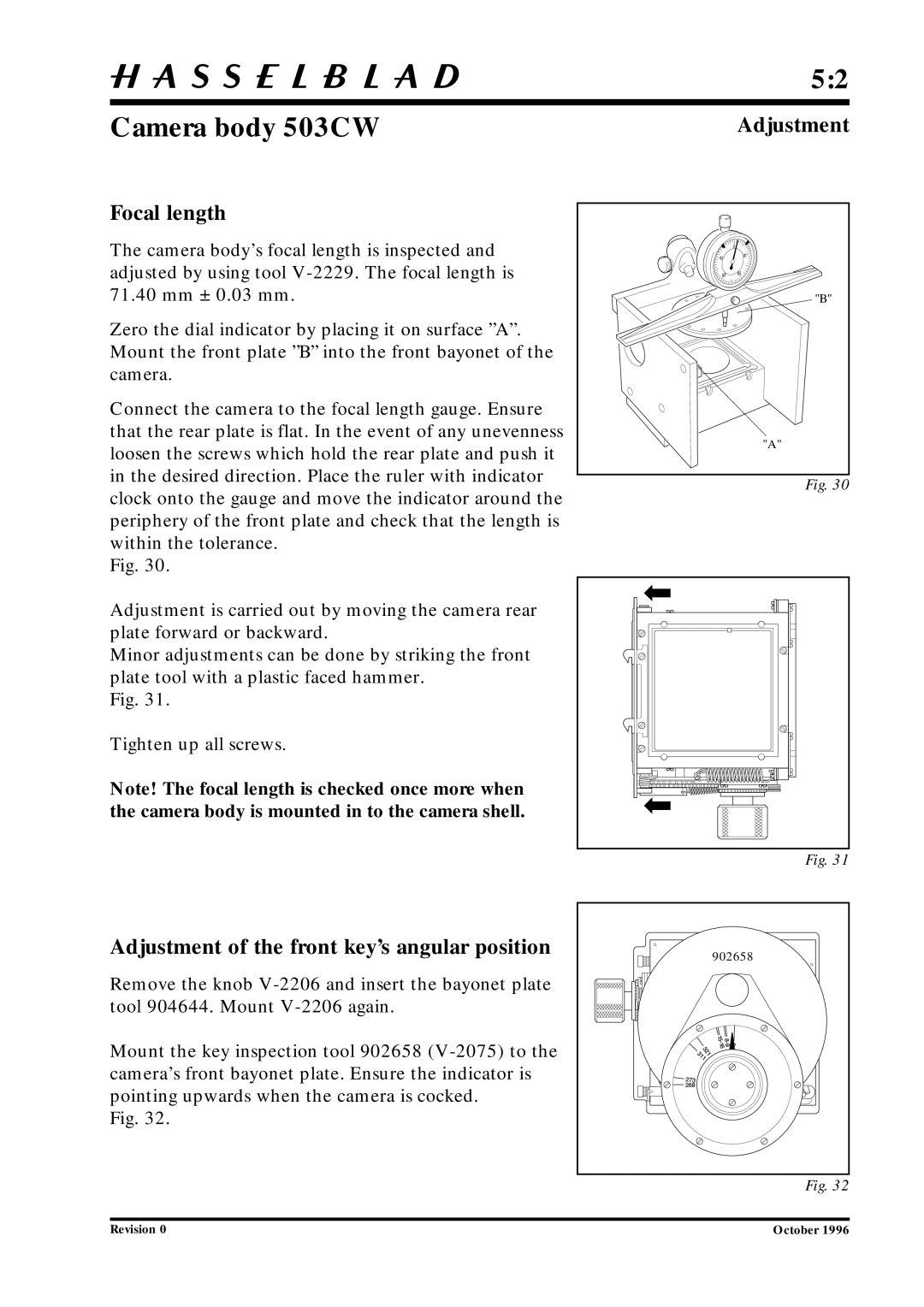
Zero the dial indicator by placing it on surface ”A”. |
| |
Mount the front plate ”B” into the front bayonet of the |
| |
camera. |
| |
Connect the camera to the focal length gauge. Ensure |
| |
that the rear plate is flat. In the event of any unevenness | "A" | |
loosen the screws which hold the rear plate and push it | ||
| ||
in the desired direction. Place the ruler with indicator | Fig. 30 | |
clock onto the gauge and move the indicator around the | ||
| ||
periphery of the front plate and check that the length is |
| |
within the tolerance. |
| |
Fig. 30. |
|
Adjustment is carried out by moving the camera rear plate forward or backward.
Minor adjustments can be done by striking the front plate tool with a plastic faced hammer.
Fig. 31.
Tighten up all screws.
Note! The focal length is checked once more when the camera body is mounted in to the camera shell.
Fig. 31
Adjustment of the front key’s angular position
Remove the knob
Mount the key inspection tool 902658
Fig. 32.
902658 |
Fig. 32
Revision 0 | October 1996 |
