6:1
Camera body 503CW
Front plate reassembly
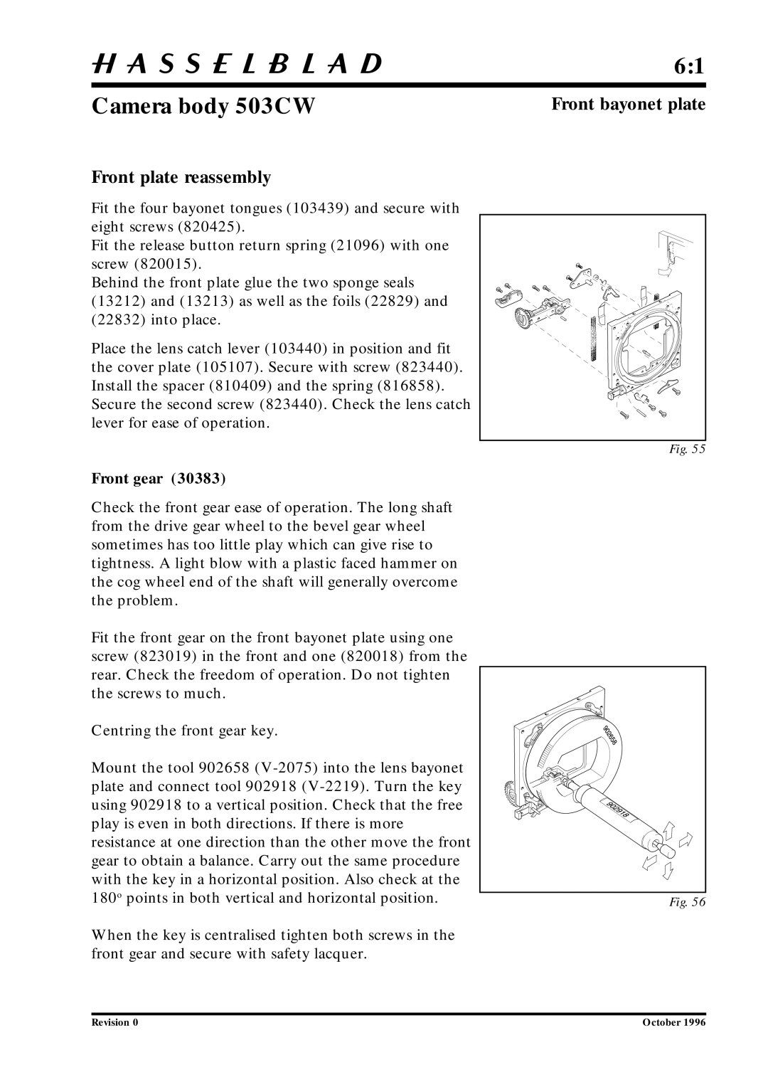
Fit the four bayonet tongues (103439) and secure with eight screws (820425).
Fit the release button return spring (21096) with one screw (820015).
Behind the front plate glue the two sponge seals (13212) and (13213) as well as the foils (22829) and
(22832) into place.
Place the lens catch lever (103440) in position and fit the cover plate (105107). Secure with screw (823440). Install the spacer (810409) and the spring (816858). Secure the second screw (823440). Check the lens catch lever for ease of operation.
Front gear (30383)
Check the front gear ease of operation. The long shaft from the drive gear wheel to the bevel gear wheel sometimes has too little play which can give rise to tightness. A light blow with a plastic faced hammer on the cog wheel end of the shaft will generally overcome the problem.
Fit the front gear on the front bayonet plate using one screw (823019) in the front and one (820018) from the rear. Check the freedom of operation. Do not tighten the screws to much.
Centring the front gear key.
Mount the tool 902658
When the key is centralised tighten both screws in the front gear and secure with safety lacquer.
Front bayonet plate
Fig. 55
Fig. 56
Revision 0 | October 1996 |