Specifications (Subject to change without notice.)
| Weld |
| Weld |
|
| Max. Open- |
| Sound Levels at |
|
| |
Welding | Stations | Weld | Output | Weld Output Rated | Circuit | Generator Output Rated | Rated Output, |
| Weight | ||
Mode | Available | Output | Range | at 104˚ F (40˚ C) | Voltage | at 104˚ F (40˚ C) | 7 m (23 ft) | Dimensions | Without Fuel* | ||
|
|
|
|
|
|
|
|
|
|
|
|
Single | 1 | CC/DC | 30 | – 600 A | 550 A at 30 VDC, | 85 | Peak: 5500 watts | 83 dB (108 Lwa) | H: | Net: 2005 lb | |
| (Right side) |
|
|
| 40% Duty Cycle |
| Continuous: 4000 watts, |
| (1210 mm) | (909 kg) | |
|
|
|
|
|
|
|
| 34/17 A, 120/240 VAC, |
| W: | Ship: 2032 lb |
Dual | 1 or 2 | CC/DC | 15 | – 300 A | 275 A at 31 VDC, |
| 85 |
| |||
while welding |
| (794 mm) | (922 kg) | ||||||||
| (Both sides) | CV/DC | 10 | – 32 V | 40% Duty Cycle | 49 |
| ||||
|
|
| D: |
| |||||||
|
|
|
|
|
|
| |||||
|
|
|
|
|
|
|
|
|
|
| |
|
|
|
|
|
|
|
|
|
| (1537 mm) |
|
|
|
|
|
|
|
|
|
|
|
|
|
*Additional 176 lb (80 kg) when fuel tank is full.
Engine (Subject to change without notice.)
|
|
|
|
|
| Weld | Fuel | Oil | Coolant | Automatic Engine |
Engine Brand | Features | HP | Type | Speed | Capacity | Capacity | Capacity | Shutdown | ||
|
|
|
|
|
|
|
|
|
|
|
|
|
| Tier IV: | 49.3 | 1800 RPM | 25 gal | 9 qt | Air | High oil | |
|
|
| cooled engine. |
| industrial, air- | Idle: N/A | (95 L) | (8.5 L) |
| temperature |
|
|
| service intervals of 500 hours for oil and |
| cooled, diesel |
|
|
|
| Low oil pressure |
Deutz, | filters. |
|
|
|
|
|
| |||
|
|
|
|
|
|
| ||||
|
|
|
|
|
|
|
|
|
|
|
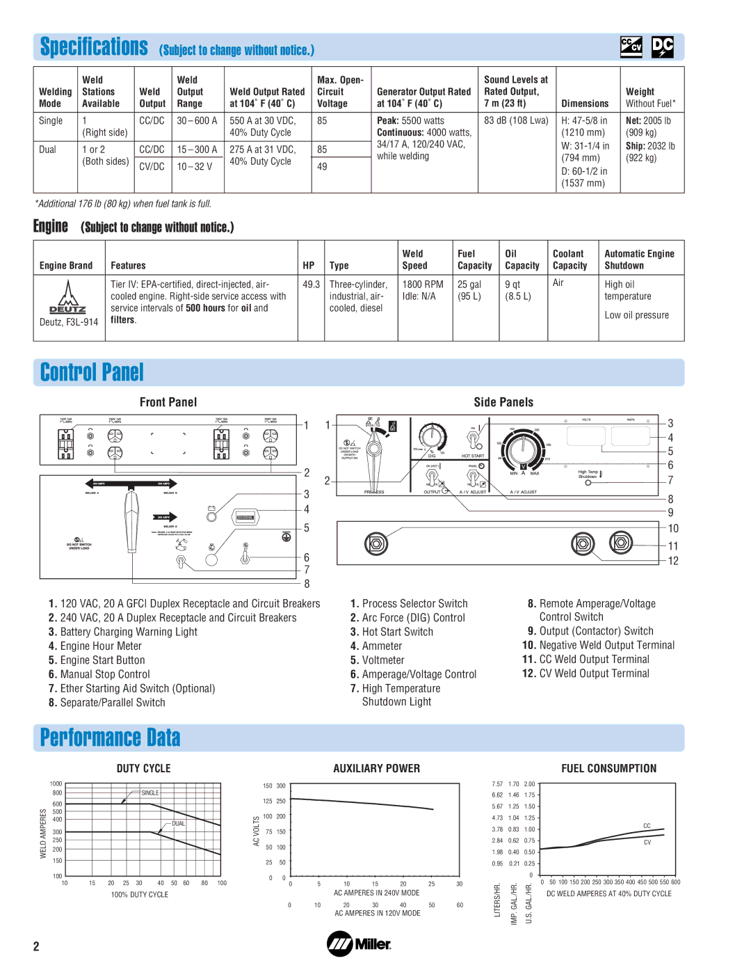
Control Panel
Front Panel |
| Side Panels | |
1 | 1 | 3 | |
|
| 4 | |
|
| 5 | |
2 |
| 6 | |
2 | 7 | ||
3 | |||
| 8 | ||
4 |
| ||
| 9 | ||
5 |
| 10 | |
6 |
| 11 | |
| 12 | ||
7 |
|
| |
8 |
|
|
1. | 120 | VAC, 20 | A GFCI Duplex Receptacle and Circuit Breakers | 1. | Process Selector Switch | 8. | Remote Amperage/Voltage |
2. | 240 | VAC, 20 | A Duplex Receptacle and Circuit Breakers | 2. | Arc Force (DIG) Control |
| Control Switch |
3. | Battery Charging Warning Light | 3. | Hot Start Switch | 9. | Output (Contactor) Switch | ||
4. | Engine Hour Meter | 4. | Ammeter | 10. | Negative Weld Output Terminal | ||
5. | Engine Start Button | 5. | Voltmeter | 11. | CC Weld Output Terminal | ||
6. | Manual Stop Control | 6. | Amperage/Voltage Control | 12. | CV Weld Output Terminal | ||
7. | Ether Starting Aid Switch (Optional) | 7. | High Temperature |
|
| ||
8. | Separate/Parallel Switch |
| Shutdown Light |
|
| ||
Performance Data
DUTY CYCLE
| 1000 |
|
|
|
|
|
|
|
|
|
| 800 |
|
|
| SINGLE |
|
|
|
| |
AMPERES | 600 |
|
|
|
|
|
|
|
|
|
500 |
|
|
|
|
|
|
|
|
| |
400 |
|
|
|
|
| DUAL |
|
| ||
|
|
|
|
|
|
|
| |||
300 |
|
|
|
|
|
|
|
|
| |
250 |
|
|
|
|
|
|
|
|
| |
WELD |
|
|
|
|
|
|
|
|
| |
200 |
|
|
|
|
|
|
|
|
| |
150 |
|
|
|
|
|
|
|
|
| |
|
|
|
|
|
|
|
|
|
| |
| 100 |
|
|
|
|
|
|
|
|
|
| 10 | 15 | 20 | 25 | 30 | 40 | 50 | 60 | 80 | 100 |
100% DUTY CYCLE
AUXILIARY POWER
| 150 | 300 |
|
|
|
|
|
|
| 125 | 250 |
|
|
|
|
|
|
VOLTS | 100 | 200 |
|
|
|
|
|
|
75 | 150 |
|
|
|
|
|
| |
AC | 50 | 100 |
|
|
|
|
|
|
|
|
|
|
|
|
| ||
| 25 | 50 |
|
|
|
|
|
|
| 0 | 0 |
|
|
|
|
|
|
|
| 0 | 5 | 10 | 15 | 20 | 25 | 30 |
AC AMPERES IN 240V MODE
0 | 10 | 20 | 30 | 40 | 50 | 60 |
AC AMPERES IN 120V MODE
FUEL CONSUMPTION
7.57 | 1.70 | 2.00 |
|
| |
6.62 | 1.46 | 1.75 |
|
| |
5.67 | 1.25 | 1.50 |
|
| |
4.73 | 1.04 | 1.25 |
|
| |
3.78 | 0.83 | 1.00 |
| CC | |
|
| ||||
2.84 | 0.62 | 0.75 |
| CV | |
1.98 | 0.40 | 0.50 |
|
| |
0.95 | 0.21 | 0.25 |
|
| |
|
| 0 | 0 | 50 100 150 200 250 300 350 400 450 500 550 600 | |
LITERS/HR. | IMP. GAL./HR. | U.S. GAL./HR. | |||
| DC WELD AMPERES AT 40% DUTY CYCLE | ||||
|
|
2