SpecificationsSymbology
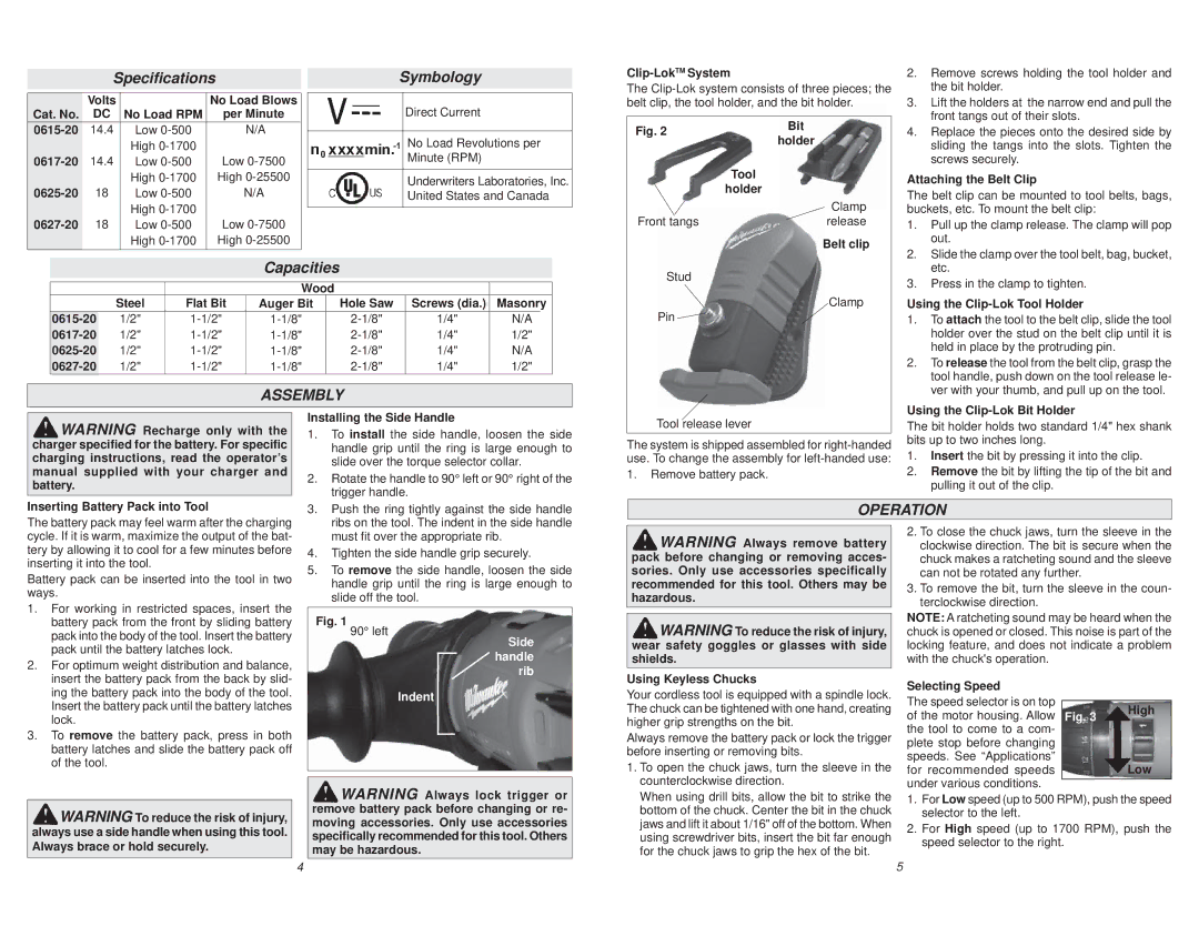
Clip-LokTM System
The
2. Remove screws holding the tool holder and |
the bit holder. |
| Volts |
| No Load Blows | |
Cat. No. | DC | No Load RPM | per Minute | |
14.4 | Low | N/A |
| |
| 14.4 | High | Low | |
Low | ||||
|
| High | High | |
18 | Low | N/A | ||
| 18 | High | Low | |
| Low | |||
|
| High | High | |
Direct Current
No Load Revolutions per Minute (RPM)
Underwriters Laboratories, Inc. United States and Canada
belt clip, the tool holder, and the bit holder.
Fig. 2 | Bit | |
holder | ||
| ||
| Tool | |
| holder | |
| Clamp | |
Front tangs | release | |
| Belt clip |
3. | Lift the holders at the narrow end and pull the |
| front tangs out of their slots. |
4. | Replace the pieces onto the desired side by |
| sliding the tangs into the slots. Tighten the |
| screws securely. |
Attaching the Belt Clip
The belt clip can be mounted to tool belts, bags, buckets, etc. To mount the belt clip:
1. | Pull up the clamp release. The clamp will pop |
| out. |
2. | Slide the clamp over the tool belt, bag, bucket, |
Capacities
|
|
| Wood |
|
|
|
| |
| Steel | Flat Bit | Auger Bit |
| Hole Saw | Screws (dia.) | Masonry | |
1/2" |
| 1/4" | N/A |
| ||||
1/2" |
| 1/4" | 1/2" |
| ||||
1/2" |
| 1/4" | N/A | |||||
1/2" |
| 1/4" | 1/2" |
| ||||
ASSEMBLY
Stud |
Clamp |
Pin |
etc. |
3. Press in the clamp to tighten. |
Using the Clip-Lok Tool Holder
1.To attach the tool to the belt clip, slide the tool holder over the stud on the belt clip until it is held in place by the protruding pin.
2.To release the tool from the belt clip, grasp the tool handle, push down on the tool release le- ver with your thumb, and pull up on the tool.
WARNING Recharge only with the charger specified for the battery. For specific charging instructions, read the operator’s manual supplied with your charger and battery.
Installing the Side Handle
1. | To install the side handle, loosen the side |
| handle grip until the ring is large enough to |
| slide over the torque selector collar. |
2. | Rotate the handle to 90° left or 90° right of the |
| trigger handle. |
Tool release lever
The system is shipped assembled for
1.Remove battery pack.
Using the Clip-Lok Bit Holder
The bit holder holds two standard 1/4" hex shank bits up to two inches long.
1.Insert the bit by pressing it into the clip.
2.Remove the bit by lifting the tip of the bit and pulling it out of the clip.
Inserting Battery Pack into Tool
3. Push the ring tightly against the side handle |
OPERATION
The battery pack may feel warm after the charging cycle. If it is warm, maximize the output of the bat- tery by allowing it to cool for a few minutes before inserting it into the tool.
Battery pack can be inserted into the tool in two ways.
1. | For working in restricted spaces, insert the |
| battery pack from the front by sliding battery |
| pack into the body of the tool. Insert the battery |
| pack until the battery latches lock. |
2. | For optimum weight distribution and balance, |
| ribs on the tool. The indent in the side handle |
| must fit over the appropriate rib. |
4. | Tighten the side handle grip securely. |
5. | To remove the side handle, loosen the side |
| handle grip until the ring is large enough to |
| slide off the tool. |
Fig. 1 90° left
Side handle rib
WARNING Always remove battery pack before changing or removing acces- sories. Only use accessories specifically recommended for this tool. Others may be hazardous.
WARNING To reduce the risk of injury, wear safety goggles or glasses with side shields.
2.To close the chuck jaws, turn the sleeve in the clockwise direction. The bit is secure when the chuck makes a ratcheting sound and the sleeve can not be rotated any further.
3.To remove the bit, turn the sleeve in the coun- terclockwise direction.
NOTE: A ratcheting sound may be heard when the chuck is opened or closed. This noise is part of the locking feature, and does not indicate a problem with the chuck's operation.
insert the battery pack from the back by slid- |
ing the battery pack into the body of the tool. |
Insert the battery pack until the battery latches |
lock. |
3. To remove the battery pack, press in both |
battery latches and slide the battery pack off |
of the tool. |
Indent
Using Keyless Chucks
Your cordless tool is equipped with a spindle lock. The chuck can be tightened with one hand, creating higher grip strengths on the bit.
Always remove the battery pack or lock the trigger before inserting or removing bits.
1. To open the chuck jaws, turn the sleeve in the |
counterclockwise direction. |
Selecting Speed
The speed selector is on top of the motor housing. Allow the tool to come to a com- plete stop before changing speeds. See “Applications” for recommended speeds under various conditions.
Fig. 3 | High |
| |
| Low |
WARNING To reduce the risk of injury, always use a side handle when using this tool. Always brace or hold securely.
WARNING Always lock trigger or remove battery pack before changing or re- moving accessories. Only use accessories specifically recommended for this tool. Others may be hazardous.
When using drill bits, allow the bit to strike the |
bottom of the chuck. Center the bit in the chuck |
jaws and lift it about 1/16" off of the bottom. When |
using screwdriver bits, insert the bit far enough |
for the chuck jaws to grip the hex of the bit. |
1.For Low speed (up to 500 RPM), push the speed selector to the left.
2.For High speed (up to 1700 RPM), push the speed selector to the right.
4 | 5 |