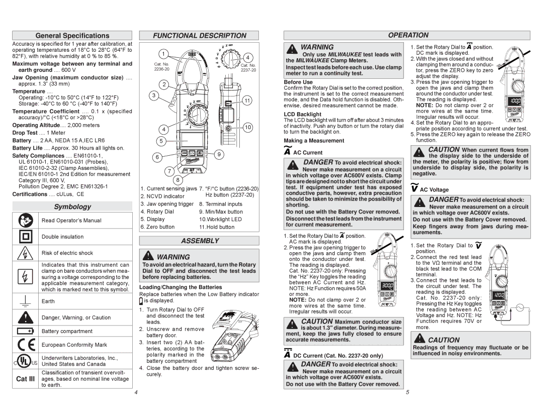
8. Terminal inputs
9. Min/Max button 10.Worklight LED 11.Hold button

General Specifications

FUNCTIONAL DESCRIPTION

OPERATION

Accuracy is specified for 1 year after calibration, at operating temperatures of 18°C to 28°C (64°F to 82°F), with relative humidity at 0 % to 85 %.

Maximum voltage between any terminal and earth ground .... 600 V

Jaw Opening (maximum conductor size) ....

approx. 1.3” (33 mm)

Temperature ....

Operating: -10°C to 50°C (14°F to 122°F)

Storage: -40°C to 60 °C (-40°F to 140°F)

Temperature Coefficient .... 0.1 x (specified

accuracy)/°C (<18°C or >28°C) Operating Altitude.... 2,000 meters

Drop Test .... 1 Meter

Battery .... 2 AA, NEDA 15 A,IEC LR6

Battery Life .... Approx. 30 Hours all lights on.

Safety Compliances .... EN61010-1,

UL 61010-1, EN61010-031 (Probes), IEC 61010-2-32 (Clamp Assemblies), IEC/EN 61010-1 2nd Edition for measurement Category III, 600 V,

1

Cat. No. 2236-20

2

3

4

5

6

7

8

4

Cat. No. 2237-20

11

10

9

WARNING

Only use MILWAUKEE test leads with the MILWAUKEE Clamp Meters.

Inspect test leads before each use. Use clamp meter to run a continuity test.

Before Use

Confirm the Rotary Dial is set to the correct position, the instrument is set to the correct measurement mode, and the Data hold function is disabled. Oth- erwise, desired measurement cannot be made.

LCD Backlight

The LCD backlight will turn off after about 3 minutes of inactivity. Push any button or turn the rotary dial to turn the backlight on.

Making a Measurement

AC Current

DANGER To avoid electrical shock: Never make measurement on a circuit in which voltage over AC600V exists. Clamp

tips are designed not to short the circuit under

1. Set the Rotary Dial to position. DC mark is displayed.

2. With the jaws closed and without clamping them around a conduc- tor, press the ZERO key to zero adjust the display. 3. Press the jaw opening trigger to open the jaws and clamp them around the conductor under test. The reading is displayed. NOTE: Do not clamp over 2 or more wires at the same time. Irregular results will occur. 4. Set the Rotary Dial to an appro-

priate position according to current under test.

5.Press the ZERO key again to release the ZERO function.

CAUTION When current flows from the display side to the underside of the meter, the polarity is positive; flow from

underside to display side, the polarity is negative.

Pollution Degree 2, EMC EN61326-1

Certifications .... cULus, CE

Symbology

Read Operator’s Manual

Double insulation

1. Current sensing jaws 7. °F/°C button (2236-20)

2. NCVD indicator Hz button (2237-20)

3. Jaw opening trigger

4. Rotary Dial

5. Display

6. Zero button

ASSEMBLY

test. If equipment under test has exposed conductive parts, however, extra precaution should be taken to minimize the possibility of shorting.

Do not use with the Battery Cover removed. Disconnect the test leads from the instrument for current measurement.

1. Set the Rotary Dial to position. AC mark is displayed.

AC Voltage

DANGER To avoid electrical shock: Never make measurement on a circuit

in which voltage over AC600V exists.

Do not use with the Battery Cover removed. Keep fingers away from jaws during mea- surements.

Risk of electric shock

Indicates that this instrument can clamp on bare conductors when mea- suring a voltage corresponding to the applicable measurement category, which is marked next to this symbol.

Earth

Danger, Warning, or Caution

Battery compartment

WARNING

To avoid an electrical hazard, turn the Rotary Dial to OFF and disconnect the test leads before replacing batteries.

Loading/Changing the Batteries

Replace batteries when the Low Battery indicator is displayed.

1. Turn Rotary Dial to OFF and disconnect the test leads.

2. Unscrew and remove

2. Press the jaw opening trigger to open the jaws and clamp them onto the conductor under test. The reading is displayed.

Cat. No. 2237-20 only: Pressing the “Hz” Key toggles the reading between AC Current and Hz. NOTE: Hz Function requires 50A or more.

NOTE: Do not clamp over 2 or more wires at the same time. Irregular results will occur.

CAUTION Maximum conductor size is about 1.3" diameter. During measure-

1.Set the Rotary Dial to position.

2.Connect the red test lead to the VΩ terminal and the black test lead to the COM terminal.

3.Connect the test leads to the circuit under test. The reading is displayed.

Cat. No. 2237-20 only: Pressing the Hz Key toggles the reading between AC Voltage and Hz. NOTE: Hz Function requires 70V or more.

AC

European Conformity Mark

Underwriters Laboratories, Inc.,

United States and Canada

Classification of transient overvolt- Cat III ages, based on nominal line voltage

to earth.

battery door.

3. Insert two (2) AA bat- teries, according to the polarity marked in the battery compartment

4.Close the battery door and tighten screw se- curely.

4

ment, keep the jaws fully closed to ensure accurate measurements.

DC Current (Cat. No. 2237-20 only)

DANGER To avoid electrical shock: Never make measurement on a circuit

in which voltage over AC600V exists.

Do not use with the Battery Cover removed.

CAUTION

Readings of frequency may fluctuate or be influenced in noisy environments.

5

Page 3
Image 3
Milwaukee 2236-20, 2237-20 manual General Specifications, Functional Description Operation, Symbology, Assembly

2236-20, 2237-20 specifications

The Milwaukee 2236-20 and 2237-20 are two advanced tools that are part of Milwaukee's RedLithium series, designed to enhance productivity and efficiency in various applications. These tools exemplify Milwaukee's dedication to innovation, durability, and user-centric design.

One of the standout features of the 2236-20 and 2237-20 is their impressive battery performance. Equipped with Milwaukee's RedLithium technology, these tools offer superior run-time, allowing users to accomplish more work on a single charge. This means less downtime spent on recharging batteries, making these tools ideal for professionals who require reliability and consistent power throughout their workday.

Both models are engineered for heavy-duty performance, utilizing high-torque motors that deliver maximum output for demanding applications. The brushless motor technology ensures not only longer tool life but also increased efficiency, providing users with the power they need without compromising on speed or performance.

The design of the Milwaukee 2236-20 and 2237-20 emphasizes user comfort and control. Ergonomically designed handles provide a secure grip, reducing fatigue during extended use. Additionally, these tools are lightweight and compact, making them easy to maneuver in tight spaces, which is particularly beneficial for plumbing, electrical, and automotive applications.

Durability is another hallmark of the Milwaukee 2236-20 and 2237-20. Built to withstand the rigors of job site conditions, they feature rugged housing and are often reinforced to resist impact and wear. This toughness ensures that the tools perform consistently regardless of the environment they are used in, making them a reliable choice for professionals.

Moreover, the Milwaukee 2236-20 and 2237-20 incorporate advanced safety features, including overload protection and electronic brake systems, which enhance user protection and tool longevity. These technologies work together to minimize the risks associated with tool use, ensuring peace of mind for users, especially in high-pressure scenarios.

In conclusion, the Milwaukee 2236-20 and 2237-20 represent the forefront of tool technology, blending power, efficiency, and durability in a user-friendly package. Whether for construction, maintenance, or any other application, these tools are designed to meet the demands of professionals who seek reliability and performance. As part of the Milwaukee family, they reflect a commitment to innovation that continues to drive the industry forward.