FUNCTIONAL DESCRIPTION
| 2 |
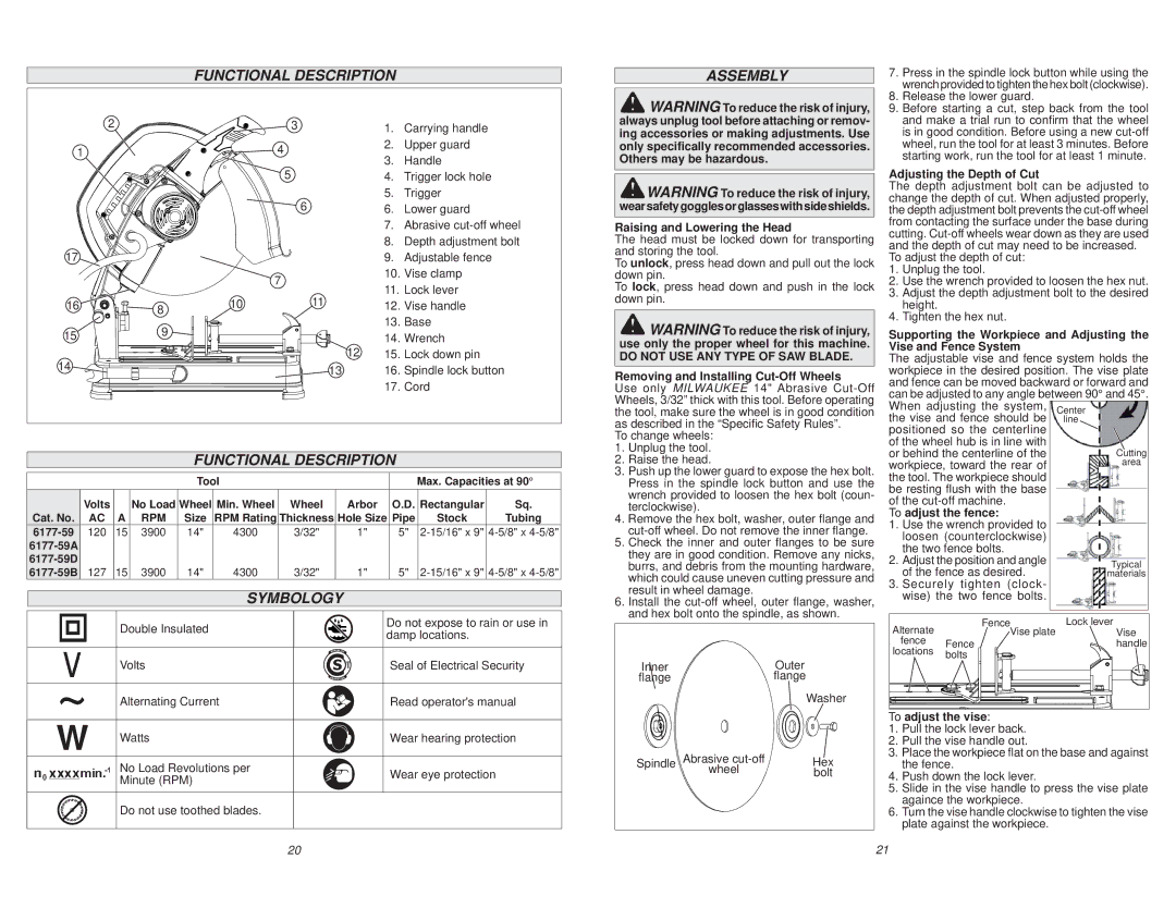
| 3 | 1. | Carrying handle |
1 |
|
| 4 | 2. | Upper guard |
|
| 3. | Handle | ||
|
|
| 5 | ||
|
|
| 4. | Trigger lock hole | |
|
|
| 6 | 5. | Trigger |
|
|
| 6. | Lower guard | |
|
|
|
| 7. | Abrasive |
17 |
|
|
| 8. | Depth adjustment bolt |
|
|
| 9. | Adjustable fence | |
|
|
| 7 | 10. | Vise clamp |
|
|
| 11. | Lock lever | |
16 |
| 10 | 11 | ||
8 | 12. | Vise handle | |||
15 | 9 |
|
| 13. | Base |
|
| 14. | Wrench | ||
|
| 12 | |||
14 |
|
| 15. | Lock down pin | |
|
| 13 | 16. | Spindle lock button | |
|
|
| |||
|
|
|
| 17. | Cord |
FUNCTIONAL DESCRIPTION
|
|
|
| Tool |
|
|
| Max. Capacities at 90° | ||
| Volts |
| No Load | Wheel | Min. Wheel | Wheel | Arbor | O.D. | Rectangular | Sq. |
Cat. No. | AC | A | RPM | Size | RPM Rating | Thickness | Hole Size | Pipe | Stock | Tubing |
120 | 15 | 3900 | 14" | 4300 | 3/32" | 1" | 5" | |||
|
|
|
|
|
|
|
|
|
| |
|
|
|
|
|
|
|
|
|
| |
127 | 15 | 3900 | 14" | 4300 | 3/32" | 1" | 5" | |||
SYMBOLOGY |
| |
|
| |
Double Insulated | Do not expose to rain or use in | |
damp locations. | ||
| ||
|
| |
Volts | Seal of Electrical Security | |
|
| |
Alternating Current | Read operator's manual | |
|
| |
W Watts | Wear hearing protection | |
No Load Revolutions per | Wear eye protection | |
Minute (RPM) | ||
| ||
|
|
Do not use toothed blades.
ASSEMBLY
![]() WARNING To reduce the risk of injury, always unplug tool before attaching or remov- ing accessories or making adjustments. Use only specifically recommended accessories. Others may be hazardous.
WARNING To reduce the risk of injury, always unplug tool before attaching or remov- ing accessories or making adjustments. Use only specifically recommended accessories. Others may be hazardous.
![]()
![]() WARNING To reduce the risk of injury, wearsafetygogglesorglasseswithsideshields.
WARNING To reduce the risk of injury, wearsafetygogglesorglasseswithsideshields.
Raising and Lowering the Head
The head must be locked down for transporting and storing the tool.
To unlock, press head down and pull out the lock down pin.
To lock, press head down and push in the lock down pin.
![]() WARNING To reduce the risk of injury, use only the proper wheel for this machine.
WARNING To reduce the risk of injury, use only the proper wheel for this machine.
DO NOT USE ANY TYPE OF SAW BLADE.
Removing and Installing Cut-Off Wheels
Use only MILWAUKEE 14" Abrasive
To change wheels:
1.Unplug the tool.
2.Raise the head.
3.Push up the lower guard to expose the hex bolt. Press in the spindle lock button and use the wrench provided to loosen the hex bolt (coun- terclockwise).
4.Remove the hex bolt, washer, outer flange and
5.Check the inner and outer flanges to be sure they are in good condition. Remove any nicks, burrs, and debris from the mounting hardware, which could cause uneven cutting pressure and result in wheel damage.
6.Install the
Inner | Outer |
flange | flange |
Washer
Spindle | Abrasive | Hex |
| wheel | bolt |
7.Press in the spindle lock button while using the wrench provided to tighten the hex bolt (clockwise).
8.Release the lower guard.
9.Before starting a cut, step back from the tool and make a trial run to confirm that the wheel is in good condition. Before using a new
Adjusting the Depth of Cut
The depth adjustment bolt can be adjusted to change the depth of cut. When adjusted properly, the depth adjustment bolt prevents the
To adjust the depth of cut:
1.Unplug the tool.
2.Use the wrench provided to loosen the hex nut.
3.Adjust the depth adjustment bolt to the desired height.
4.Tighten the hex nut.
Supporting the Workpiece and Adjusting the Vise and Fence System
The adjustable vise and fence system holds the workpiece in the desired position. The vise plate and fence can be moved backward or forward and can be adjusted to any angle between 90° and 45°. When adjusting the system,
the vise and fence should be positioned so the centerline of the wheel hub is in line with
or behind the centerline of the workpiece, toward the rear of the tool. The workpiece should be resting flush with the base of the
To adjust the fence:
1.Use the wrench provided to loosen (counterclockwise) the two fence bolts.
2. Adjust the position and angle of the fence as desired.
3.Securely tighten (clock- wise) the two fence bolts.
Alternate | FenceVise plate | Lock lever |
Vise | ||
fence | Fence | handle |
locations | bolts |
|
|
|
To adjust the vise:
1.Pull the lock lever back.
2.Pull the vise handle out.
3.Place the workpiece flat on the base and against the fence.
4.Push down the lock lever.
5.Slide in the vise handle to press the vise plate againce the workpiece.
6.Turn the vise handle clockwise to tighten the vise plate against the workpiece.
20 | 21 |