TOOL ASSEMBLY
![]()
![]()
![]()
![]() WARNING!
WARNING!
To reduce the risk of injury, always unplug tool before attaching or removing accessories or making adjustments. Use only specifically recommended accessories. Others may be hazardous.
Removing and Replacing
Select Models
MILWAUKEE's exclusive
Fig. 1
1.To remove the
2.To replace the
Installing the Side Handle
The side handle may be installed on the top of the gear case or on either side of gear case for right or left handed use. Position side handle in the location which offers best control and guard protection. For operating zones that pro- vide maximum protection for the operator, see Fig. 9. To install, thread side handle into side handle socket on desired side of gear case and tighten securely.
![]()
![]()
![]() WARNING!
WARNING!
To reduce the risk of injury when grinding, ALWAYS use the proper guard. ALWAYS properly install the guard.
Installing, Adjusting, and Removing the Guard (Fig. 2 & 3) Select Models
The guard must be used when using the tool as a grinder. The guard should be removed when using tool as a sander.
1.To install the guard, unplug the tool and place it upside down on a level surface. Remove any accessories from the spindle.
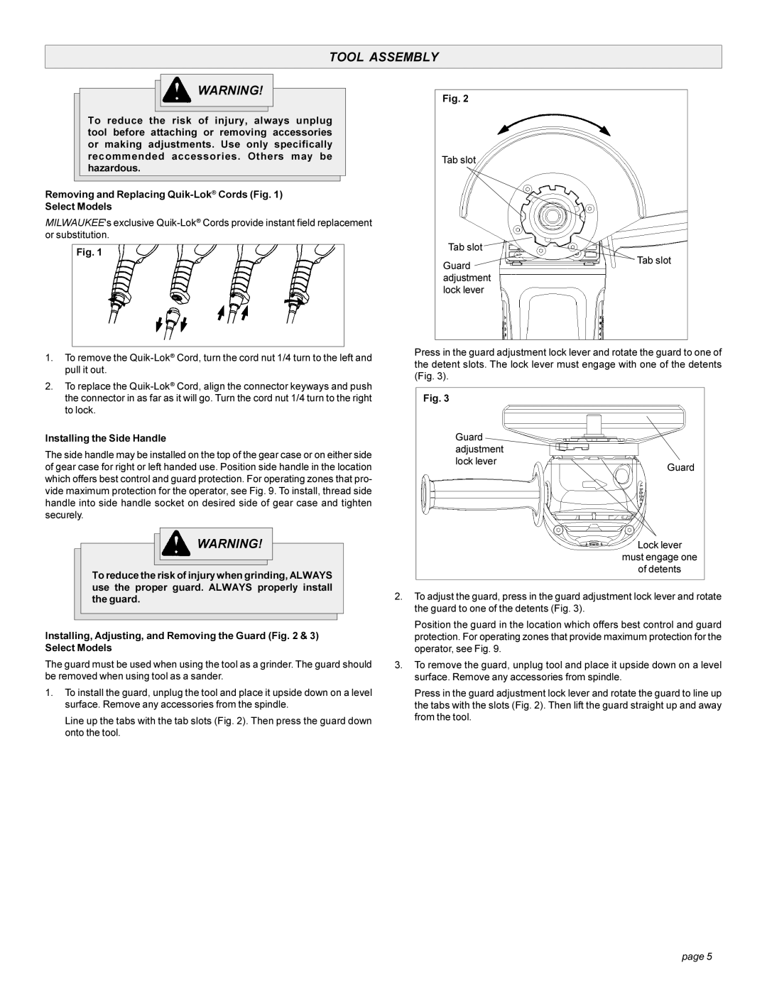
Line up the tabs with the tab slots (Fig. 2). Then press the guard down onto the tool.
Fig. 2
Tab slot
Tab slot
GuardTab slot adjustment
lock lever
Press in the guard adjustment lock lever and rotate the guard to one of the detent slots. The lock lever must engage with one of the detents (Fig. 3).
Fig. 3
Guard |
|
adjustment |
|
lock lever | Guard |
|
Lock lever
must engage one
of detents
2.To adjust the guard, press in the guard adjustment lock lever and rotate the guard to one of the detents (Fig. 3).
Position the guard in the location which offers best control and guard protection. For operating zones that provide maximum protection for the operator, see Fig. 9.
3.To remove the guard, unplug tool and place it upside down on a level surface. Remove any accessories from spindle.
Press in the guard adjustment lock lever and rotate the guard to line up the tabs with the slots (Fig. 2). Then lift the guard straight up and away from the tool.
page 5