English
INDICATOR PANEL
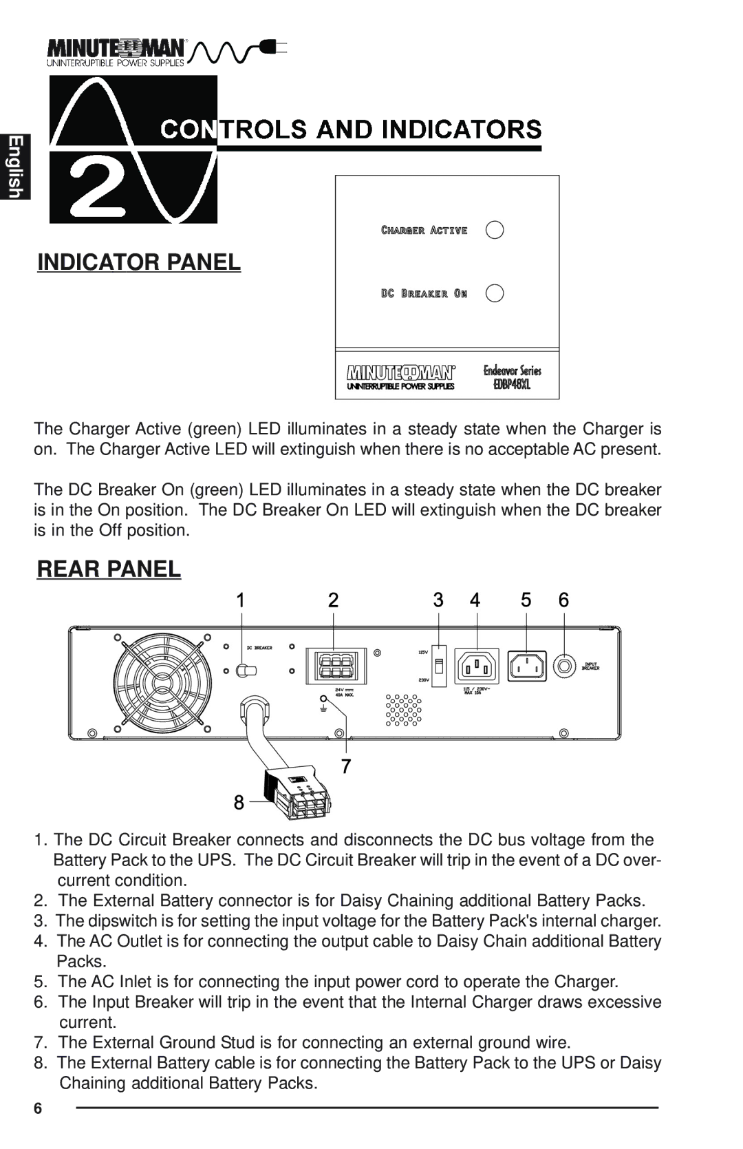
The Charger Active (green) LED illuminates in a steady state when the Charger is on. The Charger Active LED will extinguish when there is no acceptable AC present.
The DC Breaker On (green) LED illuminates in a steady state when the DC breaker is in the On position. The DC Breaker On LED will extinguish when the DC breaker is in the Off position.
REAR PANEL
1.The DC Circuit Breaker connects and disconnects the DC bus voltage from the Battery Pack to the UPS. The DC Circuit Breaker will trip in the event of a DC over- current condition.
2.The External Battery connector is for Daisy Chaining additional Battery Packs.
3.The dipswitch is for setting the input voltage for the Battery Pack's internal charger.
4.The AC Outlet is for connecting the output cable to Daisy Chain additional Battery Packs.
5.The AC Inlet is for connecting the input power cord to operate the Charger.
6.The Input Breaker will trip in the event that the Internal Charger draws excessive current.
7.The External Ground Stud is for connecting an external ground wire.
8.The External Battery cable is for connecting the Battery Pack to the UPS or Daisy Chaining additional Battery Packs.
6