3.CONTROL ELEMENTS
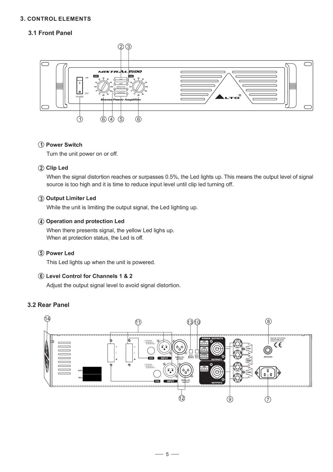
3.1Front Panel
| 2 | 3 |
|
|
| 1500 |
|
| CH1 | CH2 |
|
ON | CLIP |
|
|
|
|
| |
| LIMIT |
|
|
| OPERATING/ |
|
|
| PROTECTION |
|
|
OFF | POWER ON |
|
|
|
|
| |
POWER |
|
| R |
|
| LTO | |
| Stereo Power Amplifier | ||
|
| ||
1 | 6 | 4 | 5 | 6 |
1
2
Power Switch
Turn the unit power on or off.
Clip Led
When the signal distortion reaches or surpasses 0.5%, the Led lights up. This means the output level of signal source is too high and it is time to reduce input level until clip led turning off.
3Output Limiter Led
While the unit is limiting the output signal, the Led lighting up.
4Operation and protection Led
When there presents signal, the yellow Led lighs up. When at protection status, the Led is off.
5Power Led
This Led lights up when the unit is powered.
6Level Control for Channels 1 & 2
Adjust the output signal level to avoid signal distortion.
3.2Rear Panel
14 |
|
|
|
| 13 10 |
|
| 8 | |
11 |
|
|
|
|
|
| |||
|
|
|
|
|
|
| POWER OUTPUTS | Apparaten skall anslutas | |
|
|
|
|
|
|
|
|
| till jordat uttag nar den |
TIP/PIN 2 |
|
|
|
|
|
| CH1 | ansluts till ett natverk | |
RING/PIN 3 |
|
|
|
|
|
| 1+ | 1- |
|
SLEEVE/PIN 1 |
|
|
|
|
|
|
| ||
| NEW | TIDE | 2 | 1 |
|
| POS | NEG |
|
| 3 |
|
| 3 |
|
| CH2 | CH1 | |
| 2 | 1 |
|
|
|
| 2+ | 2- | |
|
|
|
|
|
|
|
| ||
|
|
|
|
|
|
| POS | NEG |
|
|
|
|
|
| MODE | LIMITER | BRIDGE |
| |
|
|
|
|
| 1+ | 2+ |
| ||
|
|
| PARALLEL | STEREO | OFF | BREAKER | |||
CH1 | INPUT | BRIDGE | ON | POS | NEG |
| |||
|
|
| OUTPUT |
|
|
| OUTPUT1 | BRIDGE | |
|
|
|
|
|
|
|
|
| MONO |
TIP/PIN 2 |
|
|
|
|
|
|
|
|
|
RING/PIN 3 |
|
|
|
|
|
| CH2 |
| |
SLEEVE/PIN 1 |
| NEW | TIDE | 2 | 1 |
| 1+ | 1- |
|
|
|
|
| ||||||
MODEL |
| 3 |
|
| 3 |
| POS | NEG |
|
|
| 2 | 1 |
|
|
|
|
| CH2 |
SERIAL |
|
|
|
|
|
|
|
|
|
| CH2 |
|
| PARALLEL |
|
|
|
| |
|
|
| OUTPUT |
|
| OUTPUT2 |
| ||
|
|
|
|
|
|
| |||
|
|
|
| 12 |
|
|
| 9 | 7 |
5
