Sound Projector

The TV'sbank of speakers can be adjusted to reflect sound off the room walls to create a surround sound effect. Setup can be performed manually for all models, and lor automatically depending on your TV models.

Manual Setup Option

1.From the Initial> SoundPro menu, enter the room dimensions and layout information requested in the screen. Press .... T to specify the value.

2.Highlight Custom and press ENTER to fine tune the direction and focus of the TV'ssound output.

TV Location

TVW.II

Othor Wall

TV to Sofa


length

longth


./ Center

16 feet

14 rett

12 (eet Custom

left


D


l Corner


Right


R Corner


(!)


153 and 249 Series: Select Manual option under Mode (refer to

the page 16), for Custom button to be displayed.

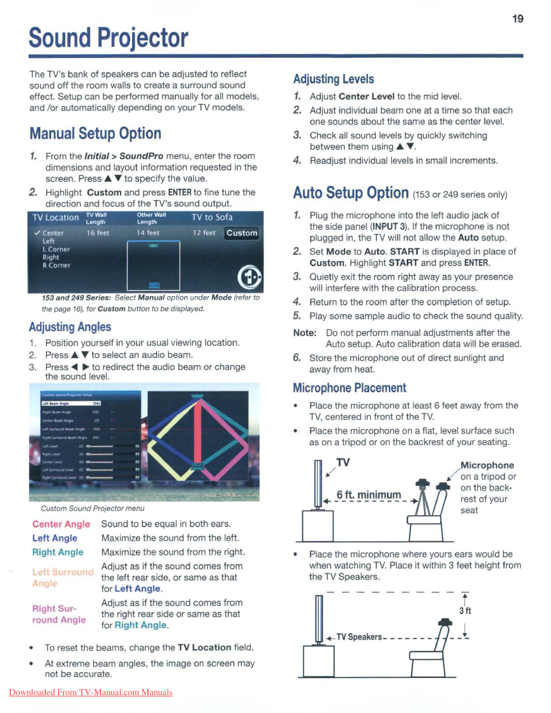
Adjusting Angles

1. Position yourself in your usual viewing location.

2.Press .... T to seiect an audio beam.

3.Press <II ~ to redirect the audio beam or change the sound level.

Custom Sound Projector menu

19

Adjusting Levels

1.Adjust Center Level to the mid level.

2.Adjust individual beam one at a time so that each one sounds about the same as the center level.

3.Check all sound levels by quickly switching between them using .... T.

4.Readjust individual levels in small increments.

Auto Setup Option (153 or 249 series only)

1.Plug the microphone into the left audio jack of the side panel (INPUT 3). If the microphone is not plugged in, the TV will not allow the Auto setup.

2.Set Mode to Auto. START is displayed in place of Custom. Highlight START and press ENTER.

3.Quietly exit the room right away as your presence will interfere with the calibration process.

4.Return to the room after the completion of setup.

5.Play some sample audio to check the sound quality.

Note: Do not perform manual adjustments after the Auto setup. Auto calibration data will be erased.

6.Store the microphone out of direct sunlight and away from heat.

Microphone Placement

Place the microphone at least 6 feet away from the TV, centered in front of the TV.

Place the microphone on a flat, level surface such as on a tripod or on the backrest of your seating.

TV


Microphone

,/

/

on a tripod or


6 ft. minimum


on the back-


rest of your

+----------+


seat

Center Angle

Left Angle

Right Angle

Right Sur- round Angle

Sound to be equal in both ears. Maximize the sound from the left. Maximize the sound from the right.

Adjust as if the sound comes from the left rear side, or same as that for Left Angle.

Adjust as if the sound comes from the right rear side or same as that for Right Angle.

Place the microphone where yours ears would be when watching TV. Place it within 3 feet height from the TV Speakers.

---------

f


3ft

..._+-..,TV Speakers-

!'!-t

To reset the beams, change the TV Location field.

At extreme beam angles, the image on screen may not be accurate.

Downloaded From TV-Manual.com Manuals

Page 19
Image 19
Mitsubishi Electronics 153, 249 Sound Projector, Adjusting Angles, Adjusting Levels, Microphone Placement, +----------+

249, 151, 153 specifications

Mitsubishi Electronics 153,249,151 is a robust model that exemplifies the company's commitment to innovation and quality in the electronics sector. Renowned for its versatility, this model is utilized across various applications, including industrial automation, consumer electronics, and communication systems.

One of the standout features of the Mitsubishi Electronics 153,249,151 is its advanced processing capability. Powered by a state-of-the-art microcontroller, it delivers high performance while ensuring energy efficiency. This is particularly beneficial for applications where power consumption is a critical consideration, allowing users to reduce their environmental impact while maintaining productivity.

The model incorporates cutting-edge communication technologies, facilitating seamless integration into existing systems. It supports multiple communication protocols, enabling interconnectivity between devices. This versatility makes the 153,249,151 suitable for diverse industries, from manufacturing to smart homes, where connectivity is paramount.

In terms of user interface, Mitsubishi Electronics has prioritized ease of use in the design of the 153,249,151. The device features an intuitive interface that provides users with quick access to its functionalities. This aspect is vital in environments where speed and efficiency are crucial, allowing operators to make adjustments or troubleshoot issues rapidly.

Another notable characteristic of the 153,249,151 is its durability. Built with high-quality materials, this model is designed to withstand the rigors of industrial use, including exposure to dust, moisture, and temperature fluctuations. This durability ensures a long operational life, reducing the need for frequent replacements and maintenance.

The 153,249,151 also integrates smart technologies, making it compatible with other smart devices. This feature enhances its functionality, allowing for automation in various operations. Users can program the model to perform tasks autonomously, increasing efficiency and reducing manual intervention.

Security is a critical concern in today’s electronic devices, and the Mitsubishi Electronics 153,249,151 addresses this with robust security features. These include encrypted communication and secure access protocols, ensuring that data transmitted between devices is safeguarded against unauthorized access.

In summary, Mitsubishi Electronics 153,249,151 is an innovative model characterized by advanced processing power, versatile communication capabilities, user-friendly design, exceptional durability, smart functionalities, and robust security features. This makes it a preferred choice for various applications, driving efficiency and high performance in today’s electronics landscape.