INTRODUCTION
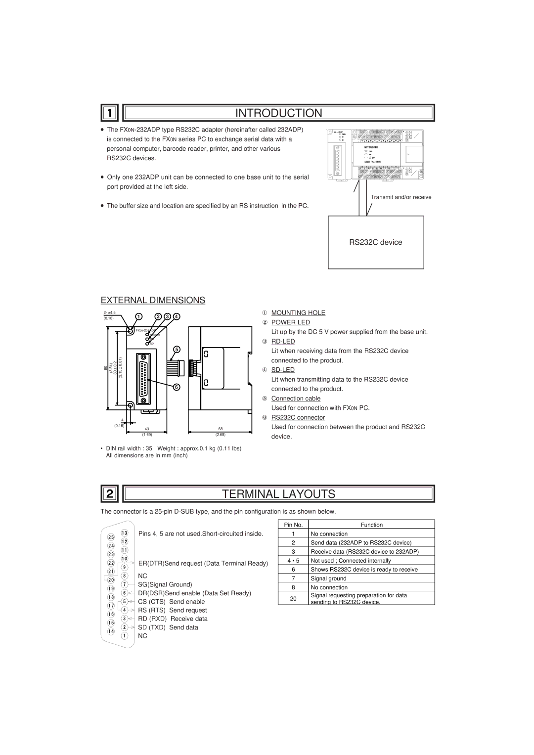
● The
● Only one 232ADP unit can be connected to one base unit to the serial port provided at the left side.
Transmit and/or receive
● The buffer size and location are specified by an RS instruction in the PC.
RS232C device
EXTERNAL DIMENSIONS
2- φ 4.5
(0.18) | 1 | 2 | 3 | 4 |
POWER
RD
SD
5
90 (3.54) 80 ± 0.2 (3.15 ± 0.01)
6
4 |
|
(0.16) | 68 |
43 | |
(1.69) | (2.68) |
• DIN rail width : 35 | Weight : approx.0.1 kg (0.11 lbs) |
All dimensions are in mm (inch)
①MOUNTING HOLE
②POWER LED
Lit up by the DC 5 V power supplied from the base unit.
③
Lit when receiving data from the RS232C device connected to the product.
④SD-LED
Lit when transmitting data to the RS232C device connected to the product.
⑤Connection cable
Used for connection with FX0N PC.
⑥RS232C connector
Used for connection between the product and RS232C device.
TERMINAL LAYOUTS
The connector is a
Pins 4, 5 are not
ER(DTR)Send request (Data Terminal Ready)
NC
SG(Signal Ground)
DR(DSR)Send enable (Data Set Ready) CS (CTS) Send enable
RS (RTS) Send request RD (RXD) Receive data SD (TXD) Send data
NC
Pin No. | Function | |
1 | No connection | |
2 | Send data (232ADP to RS232C device) | |
3 | Receive data (RS232C device to 232ADP) | |
4 • 5 | Not used ; Connected internally | |
6 | Shows RS232C device is ready to receive | |
7 | Signal ground | |
8 | No connection | |
20 | Signal requesting preparation for data | |
sending to RS232C device. | ||
|
