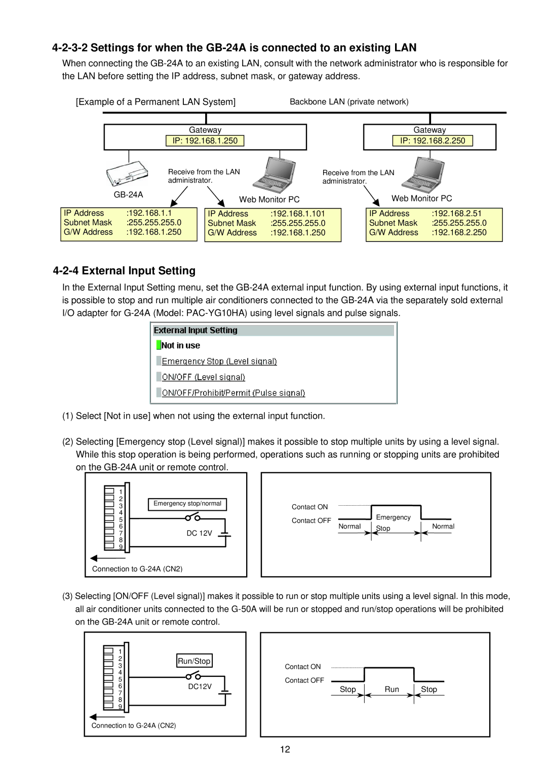
GB-24A specifications
The Mitsubishi Electronics GB-24A is a highly regarded air conditioning unit that exemplifies modern technology and efficiency. Designed for both residential and commercial applications, it offers a myriad of features that cater to the diverse needs of users while maintaining a significant focus on energy conservation and environmental sustainability.One of the standout features of the GB-24A is its remarkable efficiency rating. With a SEER (Seasonal Energy Efficiency Ratio) rating that meets and often surpasses many industry standards, this model ensures that users experience optimal cooling without incurring exorbitant energy costs. The advanced inverter technology further enhances energy savings by adjusting the compressor speed in real-time to match the desired set temperature, reducing energy consumption significantly compared to non-inverter models.
The unit is equipped with a powerful yet quiet operation mode, making it ideal for use in bedrooms or office spaces where noise levels need to be kept to a minimum. This is achieved through precision engineering and thoughtful design that minimizes vibration and operational noise.
Additionally, the GB-24A features advanced filtration systems that help to improve indoor air quality. The built-in air purifying filter removes dust, allergens, and other airborne pollutants, making it particularly beneficial for allergy sufferers and those with respiratory issues. The self-cleaning capability also aids in maintaining hygiene, as it prevents mold and bacteria build-up.
Another noteworthy characteristic is the intelligent control options provided with the GB-24A. Users can conveniently manage the climate from anywhere using a smartphone app, allowing for remote operation and programming. This feature is complemented by programmable timers and multiple operation modes, including cooling, heating, and dehumidification, making it a versatile unit for year-round use.
In terms of installation, the GB-24A is designed for flexibility. It can be mounted in various configurations, making it suitable for a range of indoor environments. This versatility, combined with its compact design, enables it to fit seamlessly into any space.
In conclusion, the Mitsubishi Electronics GB-24A stands out for its energy-efficient operation, advanced air purification technology, and smart control features. Whether for residential or commercial use, this air conditioning unit provides users with reliable performance, comfort, and peace of mind, making it a top choice in its category.

