Specifications (continued)
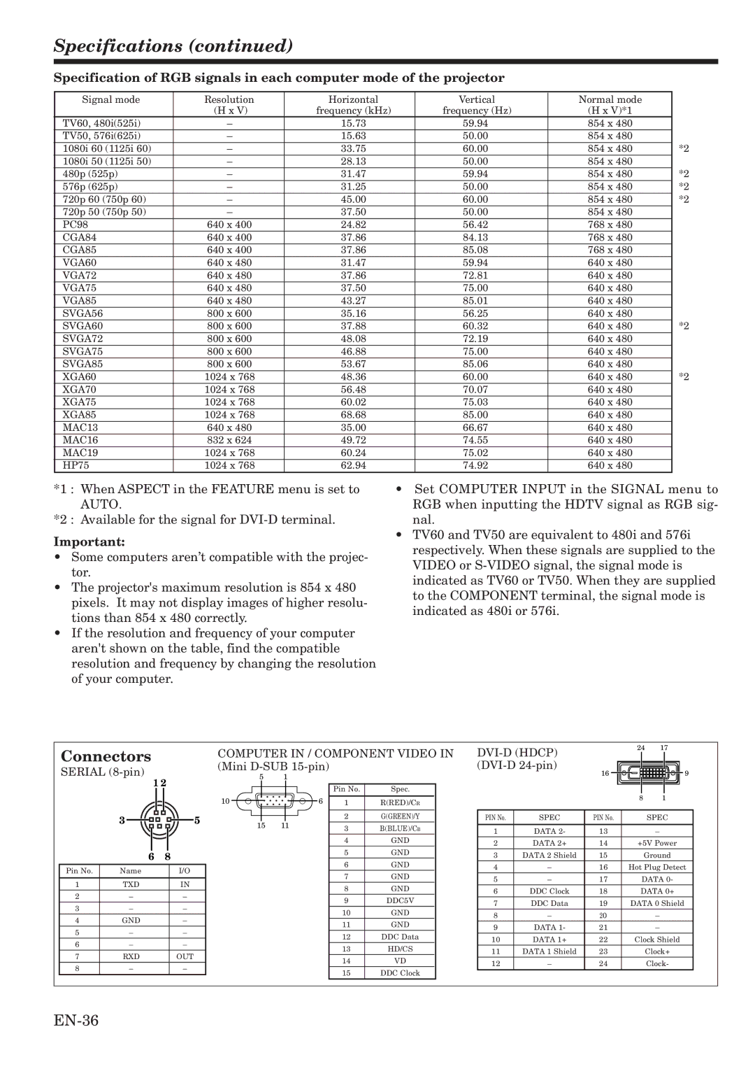
Specification of RGB signals in each computer mode of the projector
Signal mode | Resolution | Horizontal | Vertical | Normal mode |
|
| (H x V) | frequency (kHz) | frequency (Hz) | (H x V)*1 |
|
TV60, 480i(525i) | – | 15.73 | 59.94 | 854 x 480 |
|
TV50, 576i(625i) | – | 15.63 | 50.00 | 854 x 480 |
|
1080i 60 (1125i 60) | – | 33.75 | 60.00 | 854 x 480 | *2 |
1080i 50 (1125i 50) | – | 28.13 | 50.00 | 854 x 480 |
|
480p (525p) | – | 31.47 | 59.94 | 854 x 480 | *2 |
576p (625p) | – | 31.25 | 50.00 | 854 x 480 | *2 |
720p 60 (750p 60) | – | 45.00 | 60.00 | 854 x 480 | *2 |
720p 50 (750p 50) | – | 37.50 | 50.00 | 854 x 480 |
|
PC98 | 640 x 400 | 24.82 | 56.42 | 768 x 480 |
|
CGA84 | 640 x 400 | 37.86 | 84.13 | 768 x 480 |
|
CGA85 | 640 x 400 | 37.86 | 85.08 | 768 x 480 |
|
VGA60 | 640 x 480 | 31.47 | 59.94 | 640 x 480 |
|
VGA72 | 640 x 480 | 37.86 | 72.81 | 640 x 480 |
|
VGA75 | 640 x 480 | 37.50 | 75.00 | 640 x 480 |
|
VGA85 | 640 x 480 | 43.27 | 85.01 | 640 x 480 |
|
SVGA56 | 800 x 600 | 35.16 | 56.25 | 640 x 480 |
|
SVGA60 | 800 x 600 | 37.88 | 60.32 | 640 x 480 | *2 |
SVGA72 | 800 x 600 | 48.08 | 72.19 | 640 x 480 |
|
SVGA75 | 800 x 600 | 46.88 | 75.00 | 640 x 480 |
|
SVGA85 | 800 x 600 | 53.67 | 85.06 | 640 x 480 |
|
XGA60 | 1024 x 768 | 48.36 | 60.00 | 640 x 480 | *2 |
XGA70 | 1024 x 768 | 56.48 | 70.07 | 640 x 480 |
|
XGA75 | 1024 x 768 | 60.02 | 75.03 | 640 x 480 |
|
XGA85 | 1024 x 768 | 68.68 | 85.00 | 640 x 480 |
|
MAC13 | 640 x 480 | 35.00 | 66.67 | 640 x 480 |
|
MAC16 | 832 x 624 | 49.72 | 74.55 | 640 x 480 |
|
MAC19 | 1024 x 768 | 60.24 | 75.02 | 640 x 480 |
|
HP75 | 1024 x 768 | 62.94 | 74.92 | 640 x 480 |
|
*1 : When ASPECT in the FEATURE menu is set to AUTO.
*2 : Available for the signal for
Important:
•Some computers aren’t compatible with the projec- tor.
•The projector's maximum resolution is 854 x 480 pixels. It may not display images of higher resolu- tions than 854 x 480 correctly.
•If the resolution and frequency of your computer aren't shown on the table, find the compatible resolution and frequency by changing the resolution of your computer.
•Set COMPUTER INPUT in the SIGNAL menu to RGB when inputting the HDTV signal as RGB sig- nal.
•TV60 and TV50 are equivalent to 480i and 576i respectively. When these signals are supplied to the VIDEO or
Connectors
SERIAL
| 1 2 |
|
|
| |||||
| 3 |
|
|
|
|
|
|
| 5 |
|
|
|
|
|
|
|
| ||
|
|
|
|
| |||||
|
|
|
|
|
| ||||
|
|
|
|
|
|
| |||
| 6 | 8 |
|
| |||||
Pin No. | Name |
|
|
| I/O | ||||
|
|
|
|
|
| ||||
1 | TXD |
|
|
| IN | ||||
2 |
| – |
|
|
| – | |||
3 |
| – |
|
|
| – | |||
4 | GND |
|
|
| – | ||||
5 |
| – |
|
|
| – | |||
6 |
| – |
|
|
| – | |||
7 | RXD |
|
|
| OUT | ||||
8 |
| – |
|
|
| – | |||
COMPUTER IN / COMPONENT VIDEO IN (Mini
5 |
| 1 |
|
|
|
| |||
|
|
|
|
|
|
|
|
|
|
|
|
|
|
|
|
|
| Pin No. | Spec. |
10 |
|
|
|
|
|
| 6 |
|
|
|
|
|
|
|
| 1 | R(RED)/CR | ||
|
|
|
|
| |||||
|
|
|
|
|
|
|
| 2 | G(GREEN)/Y |
15 | 11 |
|
| 3 | B(BLUE)/CB | ||||
|
|
|
|
|
|
|
| ||
|
|
|
|
|
|
|
| 4 | GND |
|
|
|
|
|
|
|
| 5 | GND |
|
|
|
|
|
|
|
| 6 | GND |
|
|
|
|
|
|
|
| 7 | GND |
|
|
|
|
|
|
|
| 8 | GND |
|
|
|
|
|
|
|
| 9 | DDC5V |
|
|
|
|
|
|
|
| 10 | GND |
|
|
|
|
|
|
|
| 11 | GND |
|
|
|
|
|
|
|
| 12 | DDC Data |
|
|
|
|
|
|
|
| 13 | HD/CS |
|
|
|
|
|
|
|
| 14 | VD |
|
|
|
|
|
|
|
| 15 | DDC Clock |
|
|
| 24 | 17 |
| |||||||
|
|
|
|
|
|
|
|
|
|
| ||
| 16 |
|
|
|
|
|
|
|
|
| 9 | |
|
|
|
|
|
|
|
|
|
| |||
|
|
|
| 8 | 1 |
| ||||||
|
|
|
|
|
|
|
|
|
|
|
|
|
PIN No. | SPEC | PIN No. |
|
|
|
|
|
| SPEC | |||
|
|
|
|
|
|
|
|
|
|
|
|
|
1 | DATA 2- | 13 |
|
|
|
|
|
|
| – | ||
2 | DATA 2+ | 14 |
|
|
| +5V Power | ||||||
3 | DATA 2 Shield | 15 |
|
|
|
|
|
| Ground | |||
4 | – | 16 |
| Hot Plug Detect | ||||||||
5 | – | 17 |
|
|
|
|
| DATA 0- | ||||
6 | DDC Clock | 18 |
|
|
|
| DATA 0+ | |||||
7 | DDC Data | 19 |
| DATA 0 Shield | ||||||||
8 | – | 20 |
|
|
|
|
|
|
| – | ||
9 | DATA 1- | 21 |
|
|
|
|
|
|
| – | ||
10 | DATA 1+ | 22 |
|
| Clock Shield | |||||||
11 | DATA 1 Shield | 23 |
|
|
|
|
|
|
| Clock+ | ||
12 | – | 24 |
|
|
|
|
|
|
| Clock- | ||