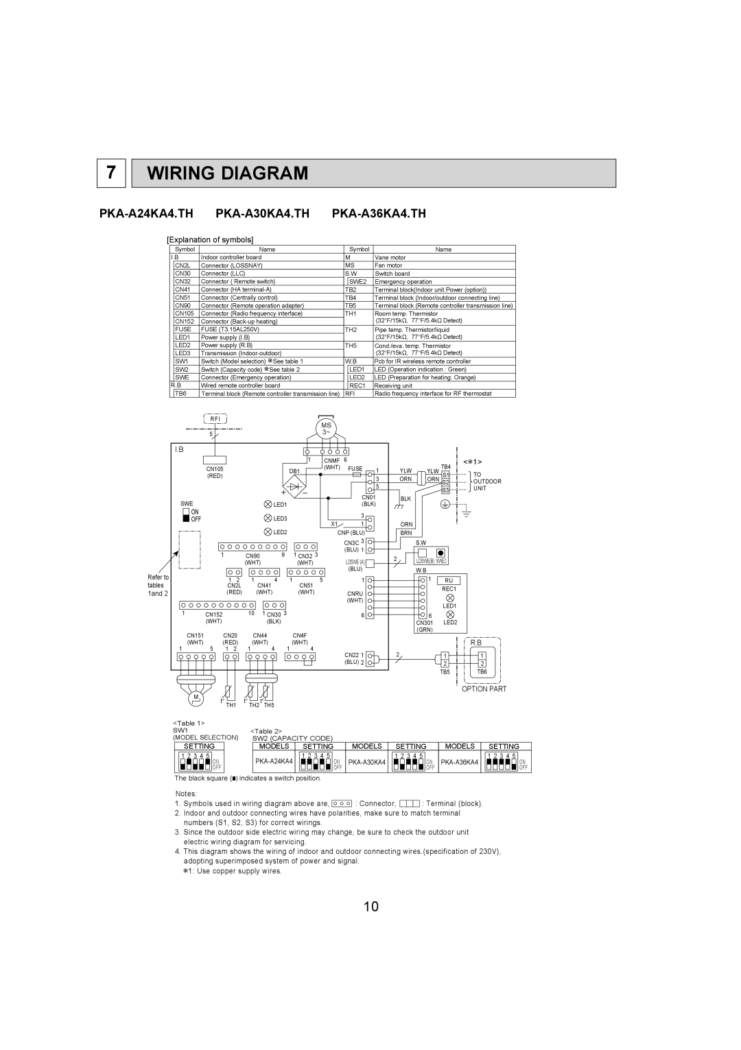
PKA-A36KA4.TH, PKA-A30KA4.TH, PKA-A24KA4.TH specifications
Mitsubishi Electronics introduces its PKA series of commercial air conditioners, comprising models PKA-A24KA4.TH, PKA-A30KA4.TH, and PKA-A36KA4.TH. These units are designed to meet the growing demand for energy-efficient and reliable climate control solutions in commercial spaces. Each model in the series is equipped with advanced features that set them apart in the competitive air conditioning market.One of the main features of the PKA series is the innovative inverter technology. This technology enables the air conditioning units to adjust their cooling or heating output according to the indoor temperature, leading to significant energy savings. By operating at varying speeds rather than a constant rate, the inverter system provides a more consistent and comfortable environment while reducing energy consumption by up to 30% compared to traditional fixed-speed systems.
Another standout characteristic of the PKA-A24KA4.TH, PKA-A30KA4.TH, and PKA-A36KA4.TH models is their compact design. These units are designed for easy installation in various commercial settings while taking up minimal space. This is particularly beneficial for businesses looking to optimize their floor space without compromising climate control efficiency.
The PKA series features advanced filtration technology, including a highly efficient air purification system. This enhances indoor air quality by removing dust, allergens, and other airborne pollutants, creating a healthier environment for occupants. The inclusion of a self-cleaning function also contributes to maintenance ease, as the unit automatically cleans the heat exchanger, preventing dust buildup and ensuring efficient operation.
Mitsubishi's commitment to whisper-quiet operation is another critical feature of these models. They are engineered to operate at sound levels as low as 19 dB(A), making them ideal for environments where noise control is essential, such as offices, hotels, or healthcare facilities.
Moreover, the PKA series is compatible with Mitsubishi's sophisticated control systems, allowing users to manage their air conditioning remotely via smartphone or tablet. This level of control enhances user convenience and maximizes system efficiency by enabling real-time adjustments based on occupancy and other factors.
Overall, the Mitsubishi Electronics PKA-A24KA4.TH, PKA-A30KA4.TH, and PKA-A36KA4.TH units represent a perfect blend of modern technology and user-centric design, providing businesses with effective, efficient, and quiet climate control solutions. With their advanced features, energy-saving capabilities, and emphasis on air quality, these models stand out as premier choices for managing environmental comfort in commercial applications.

