6. Electrical work

Function table

Select unit number 00

Mode

Settings


Mode no.

Setting no.

Initial setting

setting

Power failure automatic recovery

Not available


01

1


Available

*1

2


Indoor temperature detecting

Indoor unit operating average


1


Set by indoor unit’s remote controller


02

2


Remote controller’s internal sensor


3


LOSSNAY connectivity

Not Supported


1


Supported (indoor unit is not equipped with outdoor-air intake)

03

2


Supported (indoor unit is equipped with outdoor-air intake)


3


Power voltage

230 V


04

1


208 V


2


Auto mode (only for PUZ)

Energy saving cycle automatically enabled


05

1


Energy saving cycle automatically disabled


2


Select unit numbers 01 to 03 or all units (AL [wired remote controller]/07 [wireless remote controller])


Mode

Settings


Mode no.

Setting no.

Initial setting

setting

Filter sign

100Hr


1


2500Hr


07

2


No filter sign indicator


3


Fan speed

Standard (PLA)/Silent (PCA)


1


High ceiling 1 (PLA)/Standard (PCA)


08

2


High ceiling 2 (PLA)/High ceiling (PCA)


3


No. of air outlets

4 directions


1


3 directions


09

2


2 directions


3


Installed options (high-performance filter)

Not supported


10

1


Supported


2


Up/down vane setting

Equipped with vanes (vanes angle setup 3)


1


Equipped with vanes (vanes angle setup 1)


11

2


Equipped with vanes (vanes angle setup 2)


3


Energy saving air flow

Disabled


12

1


(Heating mode)

Enabled


2


*1 When the power supply returns, the air conditioner will start 3 minutes later.

7. Test run

7.1. Before test run

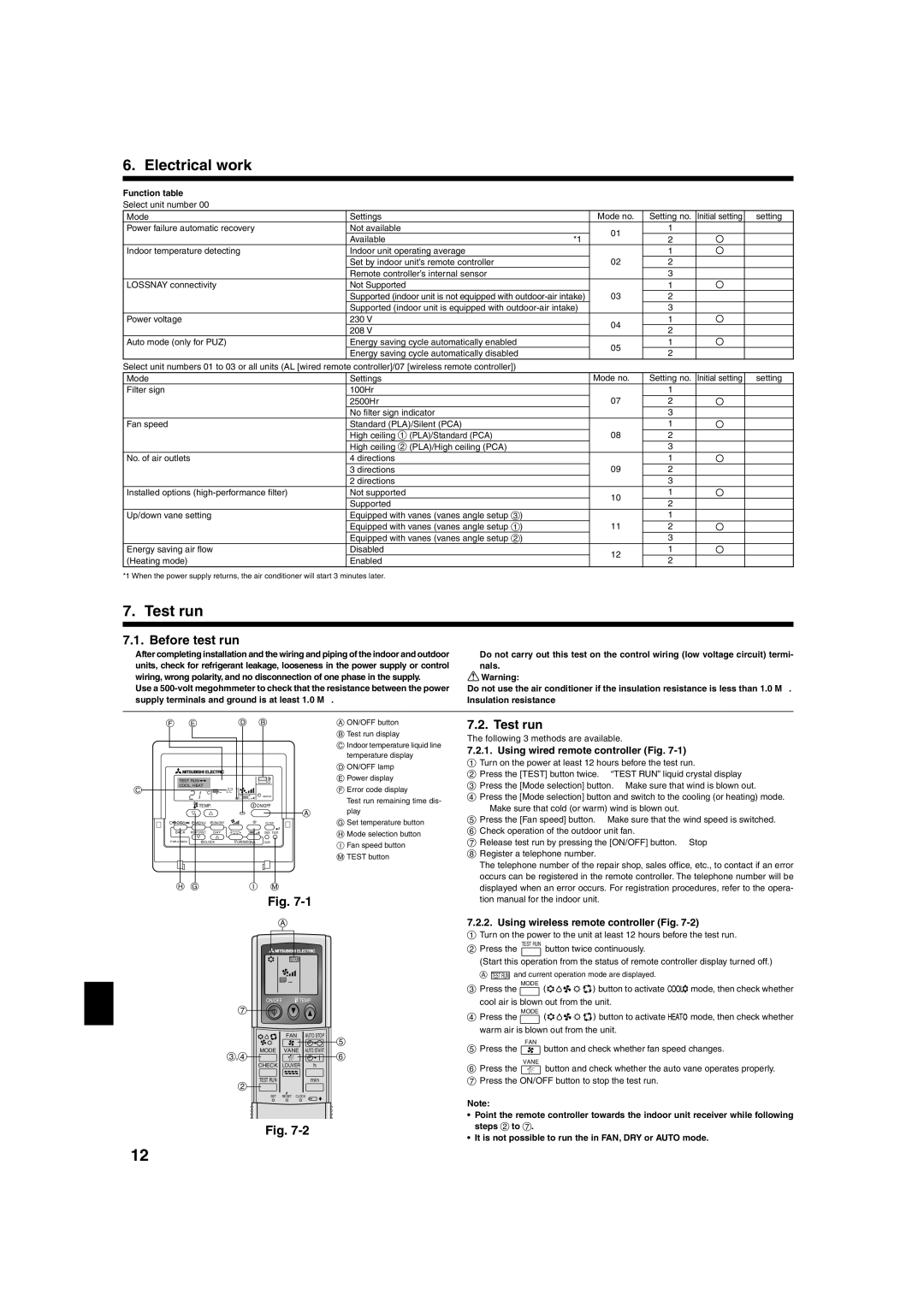
sAfter completing installation and the wiring and piping of the indoor and outdoor units, check for refrigerant leakage, looseness in the power supply or control wiring, wrong polarity, and no disconnection of one phase in the supply.

sUse a 500-volt megohmmeter to check that the resistance between the power supply terminals and ground is at least 1.0 M.

sDo not carry out this test on the control wiring (low voltage circuit) termi- nals.

Warning:

Do not use the air conditioner if the insulation resistance is less than 1.0 M.

Insulation resistance


F

E


D

B


A ON/OFF button


B Test run display


C Indoor temperature liquid line


temperature display


D ON/OFF lamp


TEST RUN


E Power display

C

COOL, HEAT


˚C


F Error code display


˚C


SIMPLE


Test run remaining time dis-


TEMP.


ON/OFF


play


A


G Set temperature button


MENU

ON/OFF


FILTER


BACK

MONITOR/SET

DAY


CHECK

TEST

H Mode selection button


PAR-21MAA

CLOCK

OPERATION

CLEAR


I Fan speed button


M TEST button


H G


I

M


Fig. 7-1


A

TEST RUN


ON/OFF

TEMP


7


FAN

AUTO STOP

5

3,4

MODE

VANE

AUTO START

6


CHECK

LOUVER

h


2

TEST RUN


min


SET

RESET CLOCK


Fig. 7-2

7.2. Test run

The following 3 methods are available.

7.2.1.Using wired remote controller (Fig. 7-1)

1 Turn on the power at least 12 hours before the test run.

2 Press the [TEST] button twice. “TEST RUN” liquid crystal display

3 Press the [Mode selection] button. Make sure that wind is blown out.

4 Press the [Mode selection] button and switch to the cooling (or heating) mode. Make sure that cold (or warm) wind is blown out.

5 Press the [Fan speed] button. Make sure that the wind speed is switched.

6 Check operation of the outdoor unit fan.

7 Release test run by pressing the [ON/OFF] button. Stop 8 Register a telephone number.

The telephone number of the repair shop, sales office, etc., to contact if an error occurs can be registered in the remote controller. The telephone number will be displayed when an error occurs. For registration procedures, refer to the opera- tion manual for the indoor unit.

7.2.2.Using wireless remote controller (Fig. 7-2)

1Turn on the power to the unit at least 12 hours before the test run.

2Press the TEST RUN button twice continuously.

(Start this operation from the status of remote controller display turned off.)

A TEST RUN and current operation mode are displayed.

3Press the MODE button to activate mode, then check whether cool air is blown out from the unit.

4Press the MODE button to activate mode, then check whether

warm air is blown out from the unit.

FAN

5Press the button and check whether fan speed changes.

VANE

6Press the button and check whether the auto vane operates properly.

7 Press the ON/OFF button to stop the test run.

Note:

Point the remote controller towards the indoor unit receiver while following steps 2 to 7.

It is not possible to run the in FAN, DRY or AUTO mode.

12

Page 12
Image 12
Mitsubishi Electronics PLA-A-AA installation manual Test run, Before test run, Using wired remote controller Fig

PLA-A-AA specifications

The Mitsubishi Electronics PLA-A-AA series is a cutting-edge range of air conditioning units designed to provide efficient cooling and heating solutions for various applications, from residential to commercial environments. This series stands out due to its innovative technology and user-friendly features.

One of the main highlights of the PLA-A-AA series is its use of advanced inverter technology. This technology allows the units to dynamically adjust their power output based on the current temperature conditions, ensuring that the desired climate is maintained efficiently. By minimizing energy consumption during operation, these systems can lead to significant savings on utility bills.

Additionally, the PLA-A-AA series is equipped with a built-in AI-driven control system that enhances user experience. This smart feature learns the user’s preferences and adjusts the operation accordingly, optimizing comfort while ensuring energy efficiency. The integration of smart technology also allows for remote control capabilities through mobile applications, enabling users to adjust settings from anywhere.

A notable characteristic of the PLA-A-AA units is their quiet operation. Designed with noise-reduction technology, these units operate at low decibel levels, making them ideal for settings where noise can be a concern, such as bedrooms and offices. This attention to sound design ensures that users can enjoy a peaceful environment without disruption.

The PLA-A-AA series also emphasizes sustainability and environmental responsibility. With a focus on using eco-friendly refrigerants, these systems have minimal impact on the environment. Mitsubishi Electronics continues to prioritize green technologies, consistently striving to reduce their carbon footprint through innovative engineering and efficiency programs.

Moreover, the units in this series are known for their durability and reliability. Constructed with high-quality materials and designed to withstand various climatic conditions, the PLA-A-AA series promises long-lasting performance. Regular maintenance is also simplified due to easily accessible components, helping to prolong the life of the unit.

In conclusion, the Mitsubishi Electronics PLA-A-AA series exemplifies the perfect blend of advanced technology, energy efficiency, and user-friendly features. With its inverter technology, smart control options, quiet operation, and commitment to sustainability, this range is an ideal choice for anyone seeking a dependable air conditioning solution.